Device and method for molding bistable magnetic alloy wire

a technology of magnetic alloy wire and device, which is applied in the manufacture of contact members, manufacturing tools, other domestic objects, etc., can solve the problems of inability to achieve continuous production, low magnetism of processed alloy wire, and relatively small deformation on the surface, so as to improve facilitate the control of the magnetic properties of alloy wire. , the effect of improving the deformation uniformity of alloy wir

Active Publication Date: 2008-03-06
ZHANG NIANRONG +5
View PDF15 Cites 3 Cited by
  • Summary
  • Abstract
  • Description
  • Claims
  • Application Information

AI Technical Summary

Benefits of technology

[0028]One advantage of the device of the invention is that during the mechanical twisting process, the alloy wire is processed by continuous repeated twisting in the forward or reverse twisting portions while moving uniformly forward; the twisting degree of the arbitrary point on the alloy wire is constant so a continuous production can be achieved; the production efficiency and the deformation uniformity of the alloy wire is improved. Furthermore, the device allows for a convenient control of the magnetic properties of the alloy wire.
[0030]By way of adding or reducing the number of the wheels, and adjusting distances between wheels, distances between a tangent point of an outer circle of a wheel and an axis of the winch, the rotating speed of the winch and the drawing speed of the alloy wire, periods and times of the forward or reverse twisting of the alloy wire can be flexibly adjusted, and thus the deformation of the shell of the alloy wire can be precisely controlled as needed, namely, the magnetic properties of the alloy wire can be controlled effectively. The twisting degree and the deformation of each part of the alloy wire are constant, and therefore the magnetic properties of the alloy wire are uniform. The device of the invention has the advantages of simple structure, artful design, high processing efficiency, and low cost.

Problems solved by technology

Disadvantages of these conventional stretching devices are: deformation on the surface is relatively small, and the magnetism of the processed alloy wire is not very high.
Conventional twisting devices need to segment alloy wires for further processing, which has the following disadvantages: 1) continuous production cannot be achieved, and processing efficiency is low; and 2) the degree of twisting and deformation of each part of the alloy wire is different, which leads to non-uniform magnetism of the alloy wire, and affects applications of the alloy wire in a precision apparatus.

Method used


Image

  • Device and method for molding bistable magnetic alloy wire
  • Device and method for molding bistable magnetic alloy wire
  • Device and method for molding bistable magnetic alloy wire

Examples


example 1

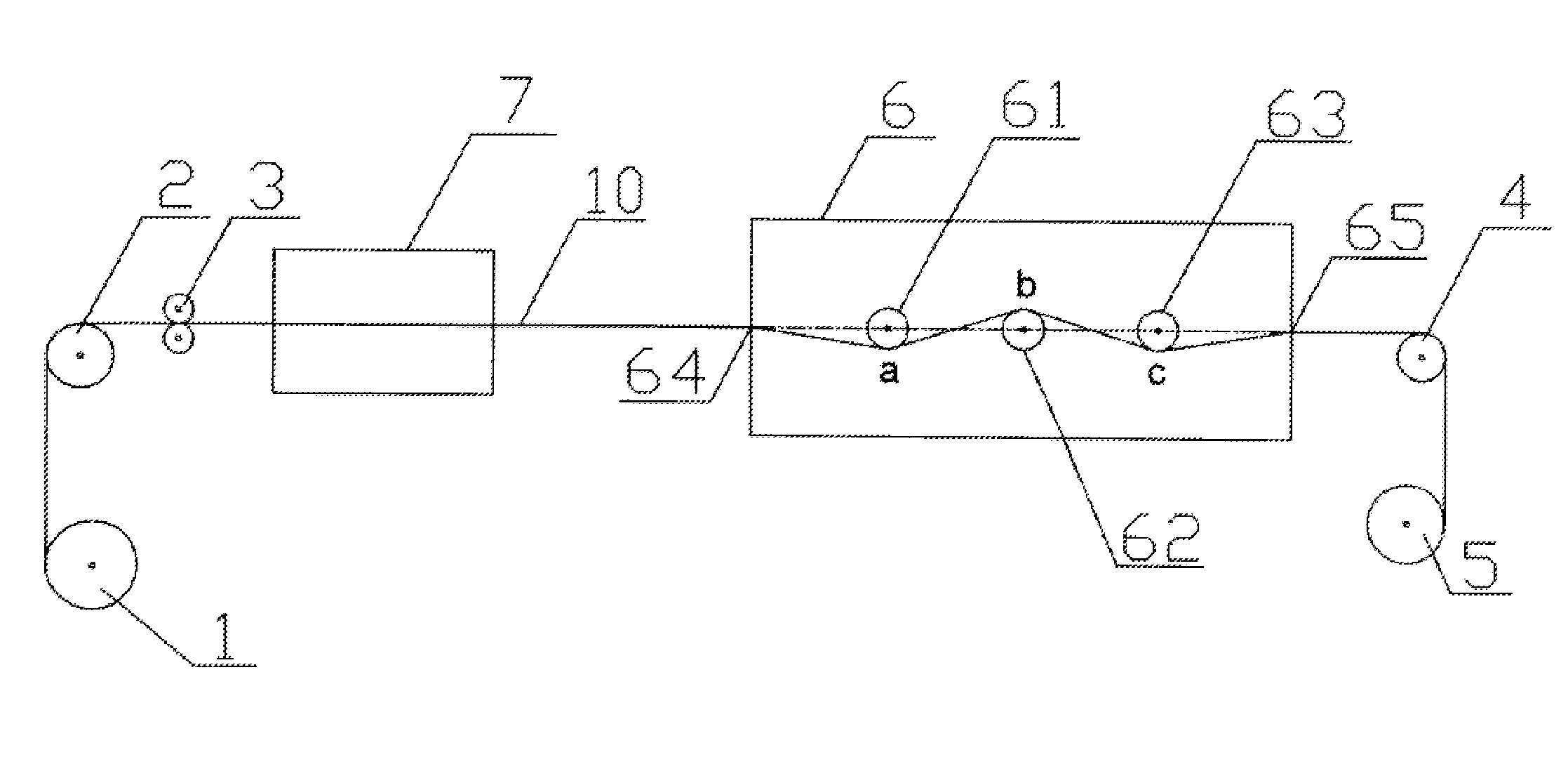
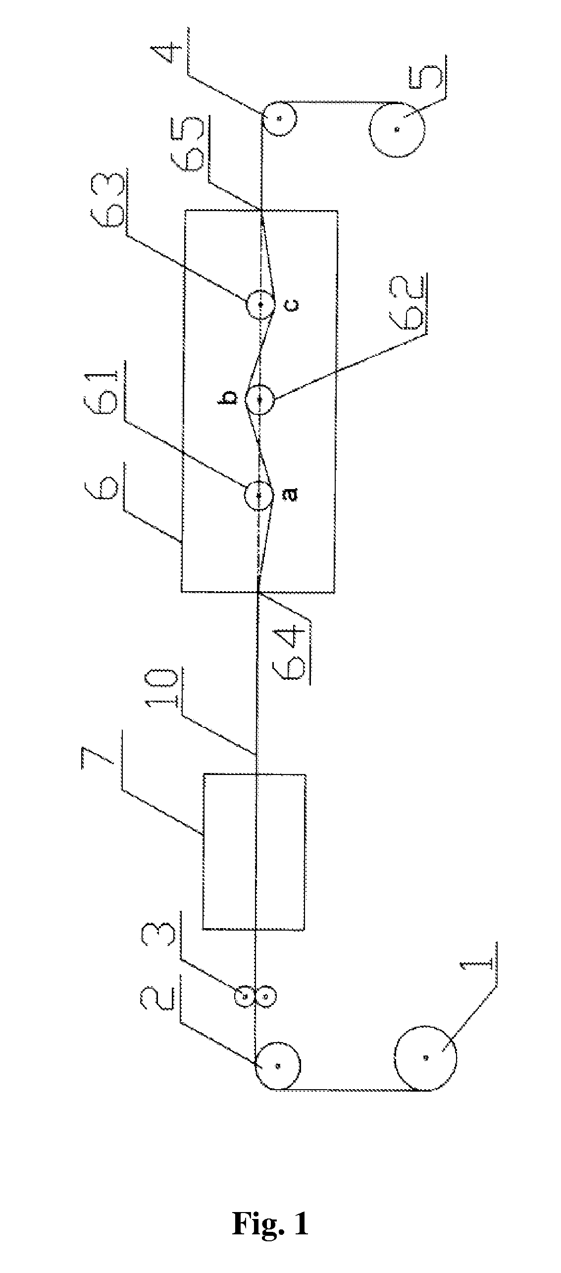
[0036]An alloy wire consisted of 49.1% Fe, 43.1% Co, 7.8% V, and a diameter of the alloy wire was 0.25 millimeters. Firstly, the alloy wire was continually processed 5 times by heat treatment (i.e. being heated up firstly and then being cooled down by air) using a radiant-type furnace, at a heat processing temperature of between 500 and 1000° C. Then, the alloy wire was processed by cold treatment of mechanical twisting: a moving speed of the alloy wire is 5 m / min, and a repeated twisting portion was composed of a forward twisting portion and an opposite twisting portion both with a length of 10 cm, and angular speeds of the two portions are 1200 loops / min. The easy magnetization direction of the bistable magnetic alloy wire was parallel to an axis of the alloy wire and was linearly-distributed (as shown in FIG. 2).

[0037]If a zero power consumption transducer made by the above material is driven by a symmetrical alternating magnetic field, the alloy wire will be magnetically switche...

example 2

[0038]An alloy wire consisted of 49.1% Fe, 43.1% Co, 7.8% V, and a diameter of the alloy wire was 0.25 millimeters. Firstly, the alloy wire was continually processed for 5 times by heat treatment (i.e. being heated up firstly and then being cooled down by air) using a radiant-type furnace, at a heat processing temperature of between 500 to 1000° C. Then, the alloy wire was processed by cold treatment of mechanical twisting: a moving speed of the alloy wire is 2 m / min, and a repeated twisting portion is composed of a forward twisting portion and an opposite twisting portion both with a length of 6 cm, and angular speeds of the two portions are 1800 loops / min. The easy magnetization direction of the bistable magnetic alloy wire was parallel to an axis of the alloy wire and was linearly-distributed (as shown in FIG. 2). If a zero power consumption transducer made by the above material is driven by a symmetrical alternating magnetic field, the alloy wire will be magnetically switched if...

example 3

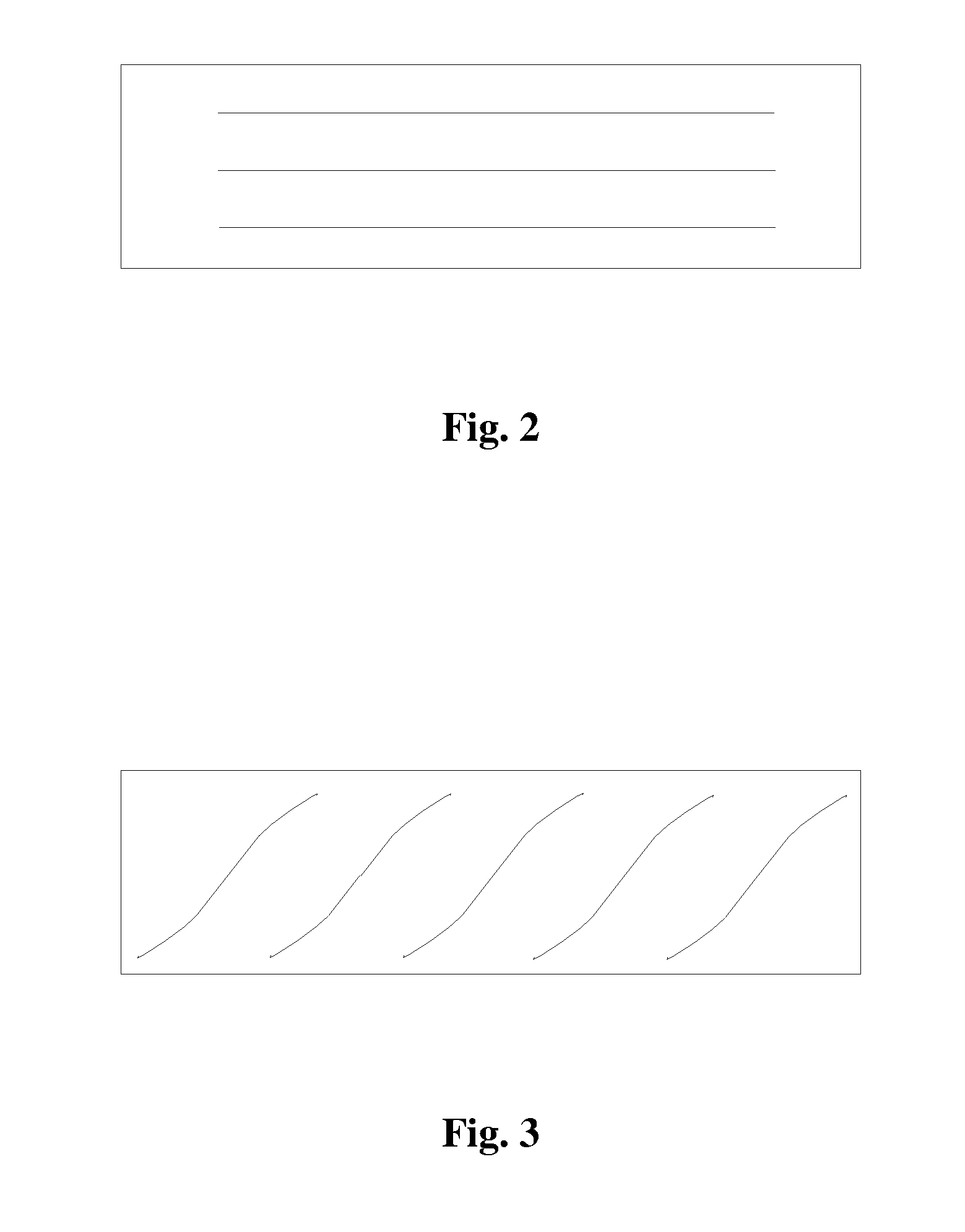
[0039]An alloy wire consisted of 49.1% Fe, 43.1% Co, 7.8% V, and a diameter of the alloy wire was 0.25 millimeters. Firstly, the alloy wire was continually processed for 5 times by heat treatment (i.e. being heated up firstly and then being cooled down by air) using a radiant-type furnace, at a heat processing temperature of between 500 to 1000° C. Then, the alloy wire was processed by cold treatment of mechanical twisting: a moving speed of the alloy wire was 0.5 m / min, and a repeated twisting portion was composed of a forward twisting portion with a length of 3 cm and an opposite twisting portion both with a length of 6 cm, and angular speeds of the two portions were 3000 loops / min. The easy magnetization direction of the bistable magnetic alloy wire was spirally-distributed (as shown in FIG. 3). If a zero power consumption transducer made by the above material is driven by a symmetrical alternating magnetic field, the alloy wire will be magnetically switched if a magnetic inducti...


PUM

PropertyMeasurementUnit
linear distanceaaaaaaaaaa
speedaaaaaaaaaa

Abstract

Taught herein is a method for molding a bistable magnetic alloy wire, comprising: processing an alloy wire by heat treatment; and processing the alloy wire by cold treatment of mechanical twisting, the mechanical twisting being a repeated twisting in a continuous state. Also taught herein is a device for molding a bistable magnetic alloy wire.

Description

CROSS-REFERENCE TO RELATED APPLICATIONS[0001]This application claims priority benefits to Chinese Patent Application No. 200610086134.5 filed on Sep. 1, 2006, the contents of which are incorporated herein by reference.BACKGROUND OF THE INVENTION[0002]1. Field of the Invention[0003]The invention relates to a device and a method for molding bistable magnetic alloy wire.[0004]2. Description of the Related Art[0005]Certain ferromagnetic alloy materials, such as Fe—Ni alloy, Fe—Co—V alloy and so on, have different magnetic properties due to different modeling methods. The greater the deformation generated by a material process, the higher the energy required to alter the state of the magnet (i.e. the coercivity will be larger); and conversely, the smaller the degree of deformation, the weaker the energy required to alter the state of the magnet (i.e. the coercivity will be smaller). In a proper technical condition, an alloy wire with uniform components can be formed into a magnetic wire ...

Claims


Application Information

Patent Timeline
Patent Type & Authority Applications(United States)
IPC IPC(8): B21C1/00H01R43/00
CPCB21F99/00C21D7/02C21D7/13C21D8/065Y10T29/5187H01R13/03H01R43/16Y10T29/49194H01R4/01
Inventor ZHANG, NIANRONGXU, HUIJUNZHU, YUNZHENG, ZHUHUICHEN, JIANYU, FANG
Owner ZHANG NIANRONG
Why Eureka
Try Eureka