Vehicle Rooftop Engine Cooling System and Method

a technology for cooling systems and engines, applied in the field of vehicles, can solve the problems of standard bus radiators/intercoolers consuming up to 50 hp of engine power, and achieve the effect of improving the efficiency of the present engine cooling system

Inactive Publication Date: 2008-03-06
SHEPPARD MULLIN RICHTER & HAMPTON
View PDF31 Cites 34 Cited by
  • Summary
  • Abstract
  • Description
  • Claims
  • Application Information

AI Technical Summary

Benefits of technology

[0006] Accordingly, an aspect of the invention relates to a new and unique vehicle rooftop engine cooling system that improves the efficiency of present engine cooling systems used on buses. The engine cooling system includes

Problems solved by technology

For example, standard bus radiators/intercoolers consume up to

Method used


Image

  • Vehicle Rooftop Engine Cooling System and Method
  • Vehicle Rooftop Engine Cooling System and Method
  • Vehicle Rooftop Engine Cooling System and Method

Examples


Embodiment Construction

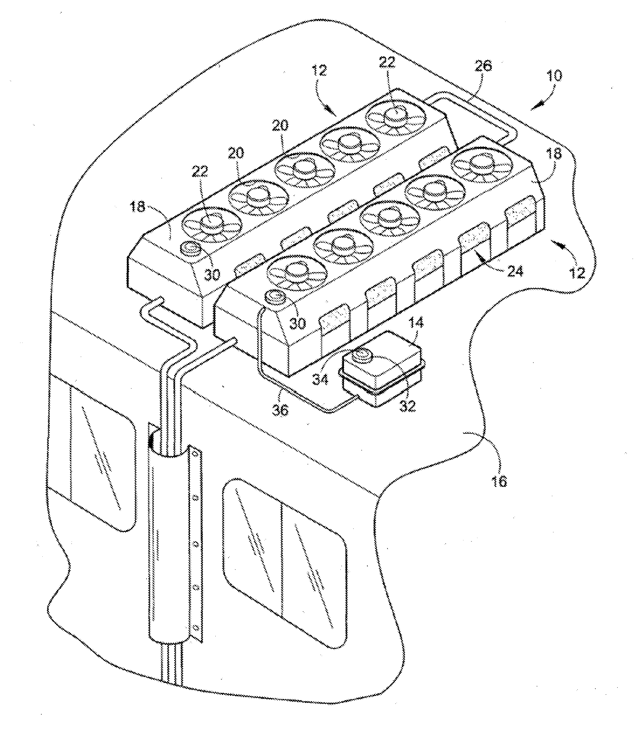
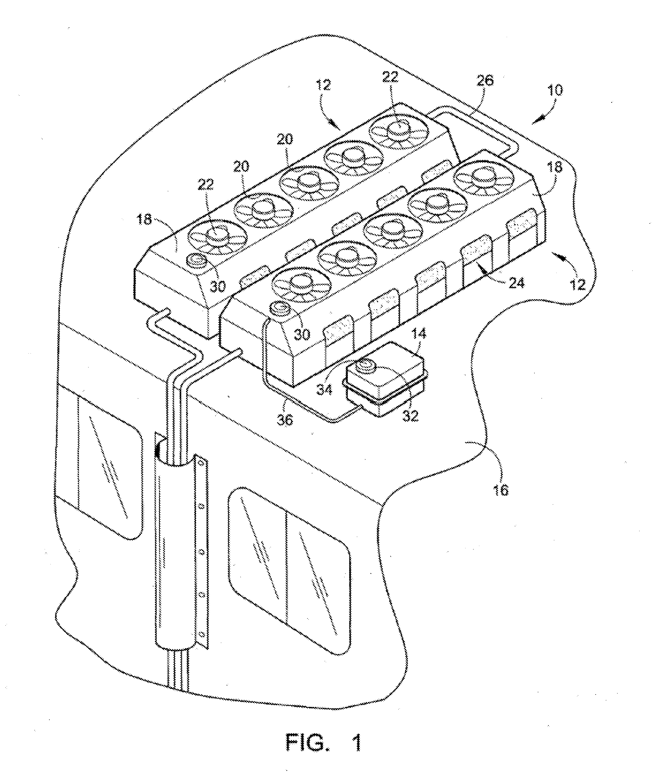
[0023] With reference to FIG. 1, an embodiment of a horizontal rooftop engine cooling system 10 will be described. The horizontal rooftop engine cooling system 10 is preferably implemented on a rooftop 11 of a bus; however, it should be fully understood that the rooftop engine cooling system 10 may be applied to the rooftop of any vehicle propelled by a propulsion system requiring cooling. Further, the rooftop engine cooling system 10 may be incorporated into new vehicles or may be a retrofitted onto existing vehicles.

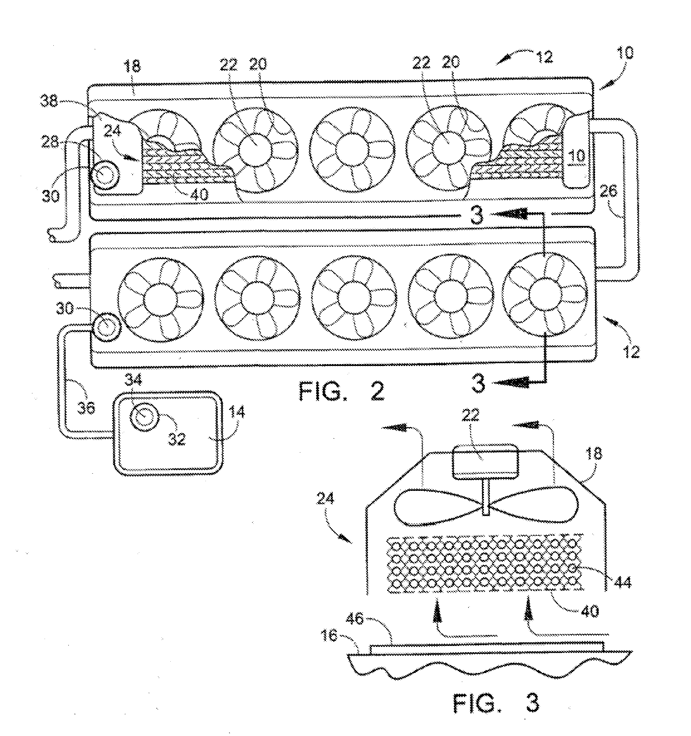
[0024] The rooftop engine cooling system 10 may include one or more horizontal radiator units 12 and an optional overflow tank 14 located on the rooftop 11 of a vehicle 16. Each horizontal radiator unit 12 may include one or more types of shrouds 18 having one or more fan orifices 20 and one or more respective electrically driven, thermostatically controlled fans 22 housed over a radiator 24.

[0025] The type of shroud 18 can be for fan mounting, aerodynamic air-flow, ...


PUM


Abstract

An vehicle rooftop cooling system includes a radiator located outside of the engine compartment of a vehicle, the radiator having a liquid coolant inside the radiator; a fan coupled to the radiator and configured to extract hot air from the radiator; a first sensor proximate to the radiator configured to measure coolant temperature of the coolant in the radiator; and a controller communicably coupled to the first sensor, the controller configured to receive inputs from the first sensor, to make determinations based on the received inputs, and to communicate control signals across a controller area network (CAN) in response to said determinations, wherein the controller is further configured to communicate a first control signal to cool the liquid coolant upon determining that the first sensor has measured temperature above a threshold.

Description

CROSS-REFERENCE TO RELATED APPLICATIONS [0001] This application is a continuation-in-part application and claims the benefit of U.S. application Ser. No. 11 / 169,184, filed on Jun. 28, 2005, which is a continuation-in-part application and claims the benefit of U.S. application Ser. No. 10 / 339,735, filed on Jan. 8, 2003, which issued as U.S. Pat. No. 6,910,529 on Jun. 28, 2005. The above applications are hereby incorporated by reference as though set forth in full.FIELD OF THE INVENTION [0002] The field of the invention relates to systems and methods for cooling motor vehicle engines and other vehicular components of transit buses (e.g., gasoline, diesel, hydrogen, electric drive transit buses). BACKGROUND OF THE INVENTION [0003] Some type of radiator or heat exchanger is normally required to remove heat from an internal combustion engine. For most applications, the power required to turn the fan that moves air through the radiator has been obtained through some mechanical, hydraulic,...

Claims


Application Information

Patent Timeline
IPC IPC(8): B60H1/32
CPCB60H1/00371B60H1/004B60H2001/00235F01P2031/00F01P7/08F01P2025/00B60K11/04
Inventor FOLLETTE, DAVIDSTONE, KEVIN
Owner SHEPPARD MULLIN RICHTER & HAMPTON
Why Eureka
Try Eureka