
Variable Cross-Coupling Partial Reflector and Method

Active Publication Date: 2008-03-06
RAYTHEON CO
View PDF8 Cites 14 Cited by
  • Summary
  • Abstract
  • Description
  • Claims
  • Application Information

AI Technical Summary

Problems solved by technology

Power is difficult to produce at millimeter wave frequencies due to the lower power output of transistors and the losses incurred by traditional power combiners at these frequencies.
For these types of arrays it is very difficult to control or modify the coupling in real time, without resorting to complicated schemes that are difficult to realize.
For quasi optical arrays that utilize cavity resonators, the oscillators are usually one port devices (negative resistance oscillators) with a single polarization output, which increases parasitic mutual coupling, creating difficulty in controlling the coupling between elements.
However, the other component of the reflected field is not controlled.
Therefore the uncontrolled component is dissipated as energy, which makes the source less efficient.

Method used


Image

  • Variable Cross-Coupling Partial Reflector and Method
  • Variable Cross-Coupling Partial Reflector and Method
  • Variable Cross-Coupling Partial Reflector and Method

Examples


case 1

co-pol=0

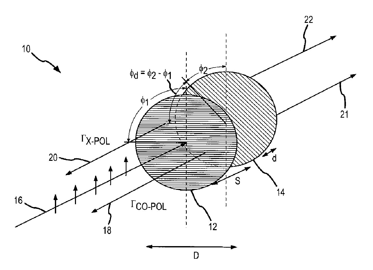
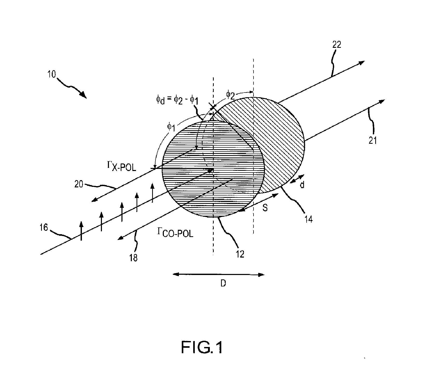
[0030]In this case the first grating is rotated by φ1=cot−1(Γx-pol) and the second grating by an amount

φd=cos-1(cos(2(φ1-π2)))

with respect to the first grating. In accordance with equation 1, φ1 will range from 45° for a maximum value of Γx-pol corresponding to 100% reflection to 90° for a minimum value of Γx-pol corresponding to 0% reflection. More typically, Γx-pol will range for −3 dB (e.g. 50% reflected power) to about −15 dB, e.g. anything less than −20 dB is essentially zero. In accordance with equation 2, φd will range from 90° for maximum x-pol reflection (e.g. 135° from the incident polarization) to 0° for minimum x-pol reflection (e.g. 90° from the incident polarization).

[0031]Another case is where the cross-pal reflected component is nulled.

case 2

x-pol=0

[0032]In this case the first grating is rotated by

φ1=π2

and the second grating by an amount

φd=cos-1(1-Γco1+Γco)

with respect to the first grating. In accordance with equation 1, φ1 is fixed for all values of co-pol reflection. In accordance with equation 2φd will range from 90° for maximum x-pol reflection (e.g. 135° from the incident polarization) to 0° for minimum x-pol reflection (e.g. 90° from the incident polarization).

[0033]The derivation of equations (1) and (2) for the partial reflector is based on the calculation of the scattering matrix for the structure. We assume that the gratings that make up the structure have been designed appropriately so that they only reflect a single Floquet mode, i.e. no grating lobes are generated. This will be the case when the grating tines are spaced less then λ / 2 apart center to center. We also assume that the gratings are designed so that the component polarized along the tines reflects perfectly (in reality there will be a small induc...


PUM


Abstract

When illuminated with a plane wave a variable cross-coupling partial reflector reflects a specific amount of a cross-polarized field and a specific amount of a co-polarized field and transmits the remaining power with low attenuation. This is achieved with a pair of frequency selective surfaces (FSS) that are rotated with respect to the incident plane wave. The FSSs can be fixed with a given alignment for a particular application or a tuning mechanism can be provided to independently rotate the surfaces and adapt the reflected co- and cross-polarized fields to changing requirements. Of particular interest is the ability to provide a specific amount of cross-polarized reflected power while reflecting no co-polarized field over a certain range of wavelengths. This will be useful to increase power efficiency in, for example, wave power sources that utilize quasi-optical power by causing oscillations in reflection amplifier arrays.

Description

BACKGROUND OF THE INVENTION[0001]1. Field of the Invention[0002]This invention relates to a partial cross-coupling reflector for use in quasi-optical millimeter wave power sources, and more specifically to a variable reflector that can select the amount of reflected power in both the co-polarized (co-pol) and cross-polarized (x-pol) fields.[0003]2. Description of the Related Art[0004]Power is difficult to produce at millimeter wave frequencies due to the lower power output of transistors and the losses incurred by traditional power combiners at these frequencies. Free space combining, also called “quasi optical” combining, eliminates the latter problem by allowing electromagnetic energy to combine in free space. Quasi optical arrays can provide high power by combining the outputs of many (e.g. thousands) of elements.[0005]Quasi optical amplifiers arranged in arrays have been developed by a number of groups to produce high output powers at millimeter wave frequencies. These amplifier...

Claims


Application Information

Patent Timeline
IPC IPC(8): H01Q15/02
CPCH01Q15/148H01Q3/46
Inventor LYNCH, JONATHAN J.
Owner RAYTHEON CO
Features
  • Generate Ideas
  • Intellectual Property
  • Life Sciences
  • Materials
  • Tech Scout
  • Unparalleled Data Quality
  • Higher Quality Content
  • 60% Fewer Hallucinations
Learn More