
Digital telescopic sight

a digital telescopic and sight technology, applied in the field of digital telescopic sight, can solve the problems of increasing the weight of the refracting prism 108, high cost, and heavy weight, and achieve the effect of reducing the weight and manufacturing cost of the present digital telescopic sight and increasing the range of applicability

Inactive Publication Date:
View PDF3 Cites 5 Cited by
  • Summary
  • Abstract
  • Description
  • Claims
  • Application Information

AI Technical Summary

Benefits of technology

[0007]An object of the present invention is to provide a digital telescopic sight that utilizes a semi-reflecting mirror to reflect a portion of the light rays onto an image sensor thereof, so that the weight and manufacturing cost of the digital telescopic sight are decreased.
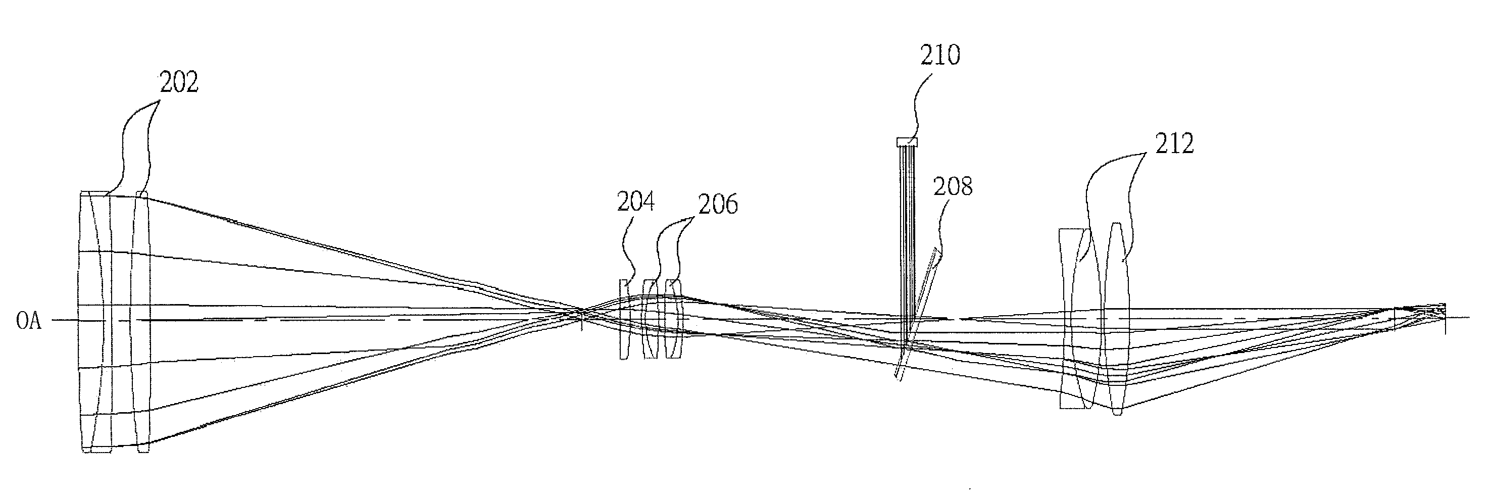
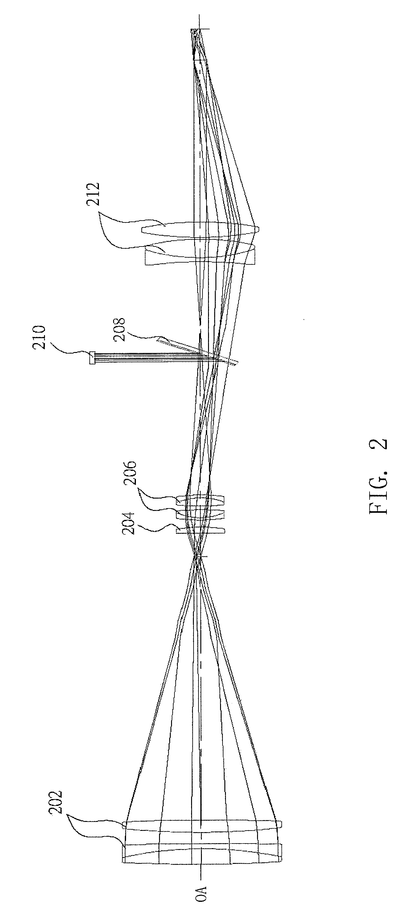
[0008]To achieve the above object of the present invention, a digital telescopic sight in accordance with the present invention includes an objective lens group, a light collecting lens, an erecting lens group, an eyepiece lens group, a semi-reflecting mirror and an image sensor. The incident exterior light rays are sequentially transmitted through the objective lens group, the light collecting lens and the erecting lens group, and then incident onto the semi-reflecting mirror. The semi-reflecting mirror reflects a portion of the light rays onto the image sensor, and transmits the remaining primary light rays to the eyepiece lens group for enabling the user to view the image. The image sensor receives the portion of the light rays reflected by the semi-reflecting mirror, converts it into an electrical signal, and finally transmits the electrical signal to a Digital Signal Processor (DSP) (not shown) for further image signal processing. The semi-reflecting mirror is formed by providing a semi-reflecting metal film on a planar mirror by means of vacuum sputtering, vapor deposition or coating. The planar mirror is made of a transparent glass or plastic material.
[0009]The present digital telescopic sight employs a semi-reflecting mirror to reflect a portion of the light rays along the primary optical axis onto the image sensor. In comparison with the conventional digital telescopic sight that employs a refracting prism, the weight and manufacturing cost of the present digital telescopic sight are reduced while without compromising the optical performance of the present digital telescopic sight. Accordingly, the present digital telescopic sight has an increased range of applicability in comparison with the conventional design.

Problems solved by technology

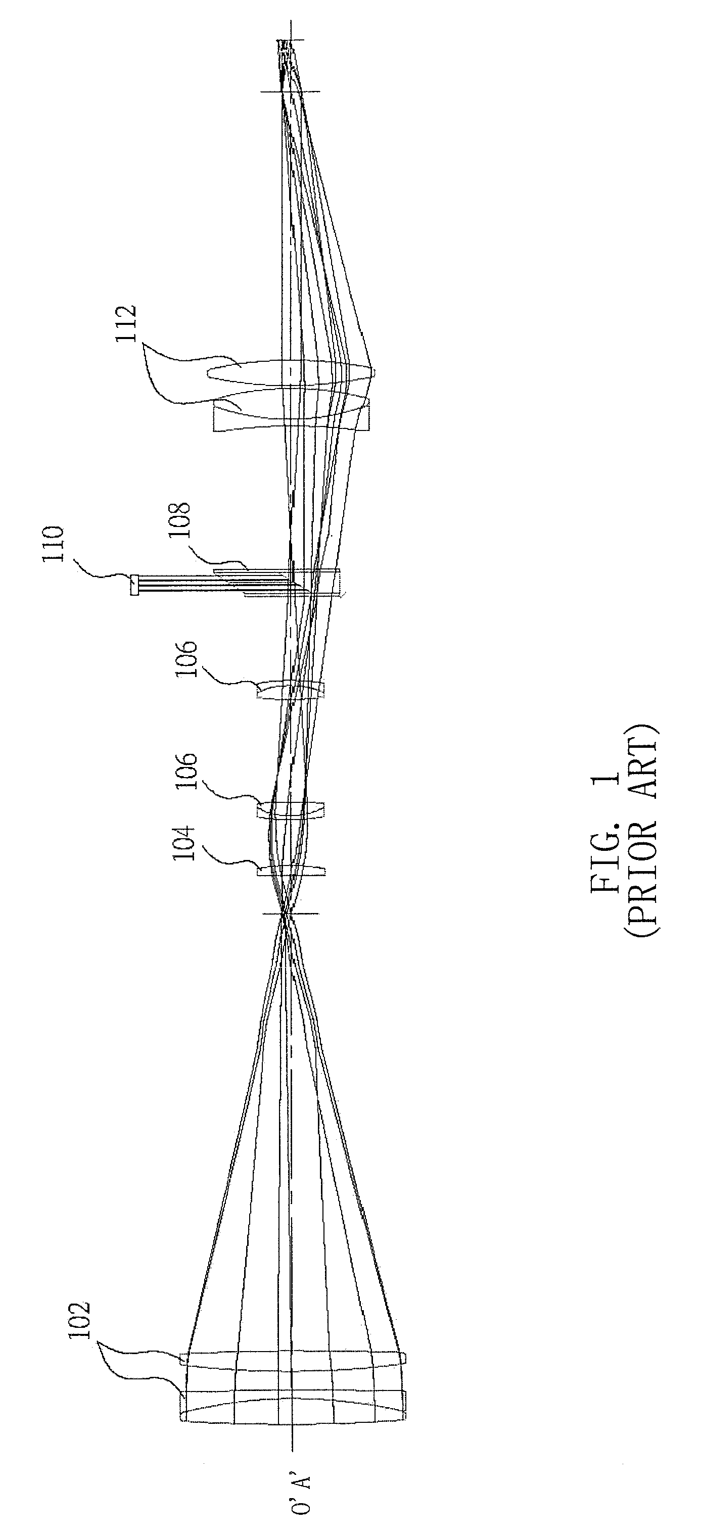
However, the refracting prism 108 is complex in structure, high in cost, and heavy in weight.
Therefore, incorporation of a refracting prism in the conventional digital telescopic sight increases the weight of the telescopic sight, complicates the configuration of the telescopic sight, and increases the manufacturing costs.

Method used


Image

  • Digital telescopic sight
  • Digital telescopic sight
  • Digital telescopic sight

Examples


Embodiment Construction

[0013]FIG. 2 is a schematic view illustrating the component configuration of a digital telescopic sight in accordance with the present invention. As shown in FIG. 2, the present digital telescopic sight includes an objective lens group 202, a light semi-reflecting mirror 208 and an image sensor 210. The objective lens group 202, the light collecting lens 204, the erecting lens group 206, the semi-reflecting mirror 208 and the eyepiece lens group 212 are sequentially arranged along the direction in which exterior light rays enter the digital telescopic sight or along the primary optical axis OA of the digital telescopic sight. In detail, the objective lens group 202 is positioned at an object end or the frontmost end of the digital telescopic sight. The light collecting lens 204 is positioned on one side of the objective lens group 202. The erecting lens group 206 is positioned on one side of the light collecting lens group 204 opposite to the objective lens group 202. The semi-refle...


PUM


Abstract

A digital telescopic sight includes an objective lens group (202), a light collecting lens (204), an erecting lens group (206), an eyepiece lens group (212), a semi-reflecting mirror (208) and an image sensor (210). The incident exterior light rays are sequentially transmitted through the objective lens group, the light collecting lens and the erecting lens group, and then incident onto the semi-reflecting mirror. The semi-reflecting mirror reflects a portion of the light rays onto the image sensor, and transmits the remaining primary light rays to the eyepiece lens group for enabling the user to view the image. The image sensor receives the reflected portion of the light rays, converts it into an electrical signal, and finally transmits the electrical signal to a digital signal processor for further image signal processing.

Description

BACKGROUND OF THE INVENTION[0001]1. Field of the Invention[0002]The present invention relates to a digital telescopic sight, and particularly relates to a digital telescopic sight that employs a semi-reflecting mirror to reflect a portion of the light rays onto an image sensor thereof.[0003]2. Description of Prior Art[0004]FIG. 1 is a schematic view illustrating the component configuration of an optical system for a conventional digital telescopic sight. This optical system primarily includes an objective lens group 102, a light collecting lens 104, an erecting lens group 106, an eyepiece lens group 112, a refracting prism 108 and an image sensor 110. The refracting prism 108 is adapted to refract a portion of the light rays along a primary optical axis O′A′ of the optical system onto the image sensor 110. The image sensor 110 may be in the form of a CMOS (Complementary Metal-Oxide Semiconductor) sensor or a CCD (Charge Coupled Device) sensor. The image sensor 110 then receives this...

Claims


Application Information

Patent Timeline
Patent Type & Authority Applications(United States)
IPC IPC(8): G02B23/00
CPCG02B23/145
Inventor CHANG, CHIA-CHUNLIN, CHEN-YEH
Learn More