

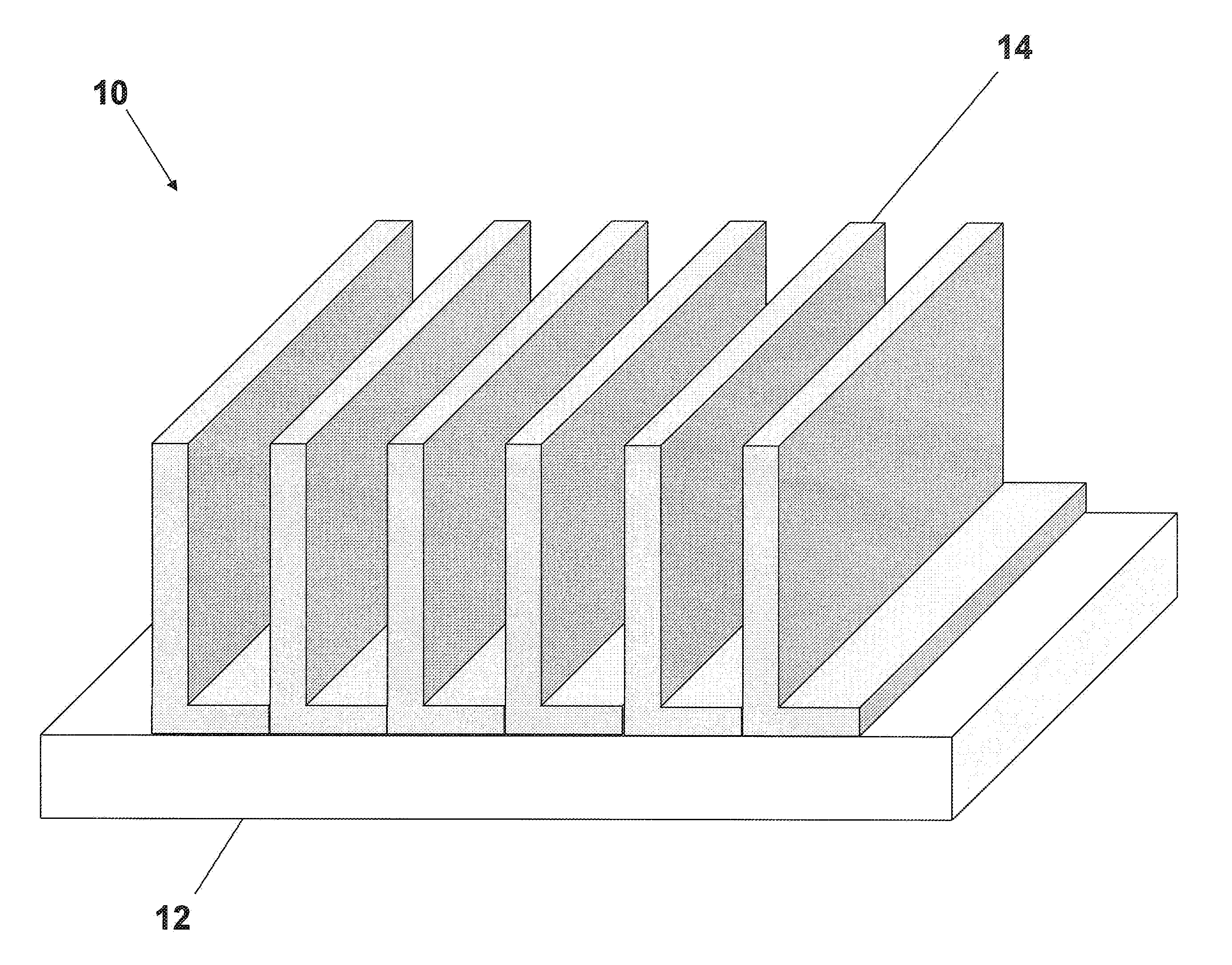
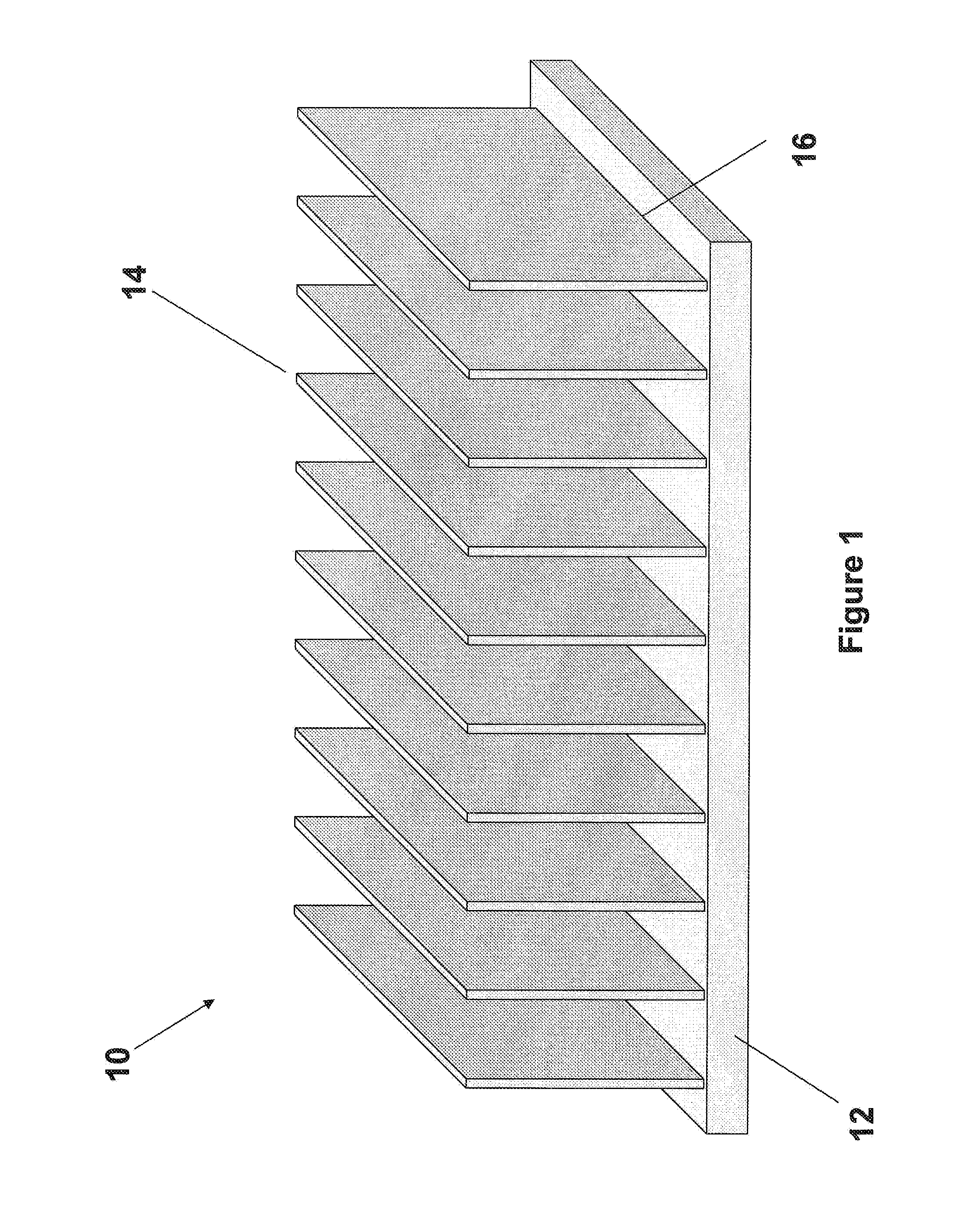
Base Heat Spreader With Fins
- Summary
- Abstract
- Description
- Claims
- Application Information
AI Technical Summary
Benefits of technology
Problems solved by technology
Method used
Image

Examples
Embodiment Construction
[0042]The thermal management device in accordance with the present invention can improve both the performance and functional lifespan of an electronic device through the reduction of the operating temperature of the device. Specifically, the invention provides for greater reduction in the temperature of the electronic device than prior art devices through improved convection, namely the transfer of thermal energy from the inventive thermal management device to the surrounding air.
[0043]In configurations including the use of a fan component, forced convection occurs as the fan imposes external motion onto the air. Forced convection provides for typically better cooling as air is continuously in motion over the heat sink and provides a larger gradient of temperatures resulting in a larger thermal flux. With the improved thermal dissipation qualities of the present invention, less airflow is necessary as the thermal management device is more efficient for a given airflow. As such, the ...
PUM
 Abstract
Description
Claims
Application Information