Beam tuning with automatic magnet pole rotation for ion implanters

a technology of ion beam and automatic rotation, applied in the field of ion beam tuning system and method, can solve the problems of insufficient focusing force, use of ion source extraction optics, and difficulty in focusing ion beams

Inactive Publication Date: 2008-03-20
AXCELIS TECHNOLOGIES
View PDF8 Cites 9 Cited by
  • Summary
  • Abstract
  • Description
  • Claims
  • Application Information

AI Technical Summary

Problems solved by technology

In such high current implanters, the ion beam is typically difficult to focus due to the space charge of the low energy associated therewith.
However, the use of ion source extraction optics, alone, has proved to be insufficient in providing the necessary focusing force for the high current ion beam along the entire beamline, and additional focusing is typically needed to achieve an acceptable ion implantation.
Furthermore, high current ion implanters typically operate in a deceleration mode with an energy filter, wherein the AMU magnet is “de-tuned”, thus resulting in a shifting of the optical focal point of the ion beam.

Method used


Image

  • Beam tuning with automatic magnet pole rotation for ion implanters
  • Beam tuning with automatic magnet pole rotation for ion implanters
  • Beam tuning with automatic magnet pole rotation for ion implanters

Examples


Embodiment Construction

[0023]The present invention is directed generally toward an ion implantation system and method for controlling a path and / or focal point of an ion beam. Accordingly, the present invention will now be described with reference to the drawings, wherein like reference numerals may be used to refer to like elements throughout. It should be understood that the description of these aspects are merely illustrative and that they should not be interpreted in a limiting sense. In the following description, for purposes of explanation, numerous specific details are set forth in order to provide a thorough understanding of the present invention. It will be evident to one skilled in the art, however, that the present invention may be practiced without these specific details.

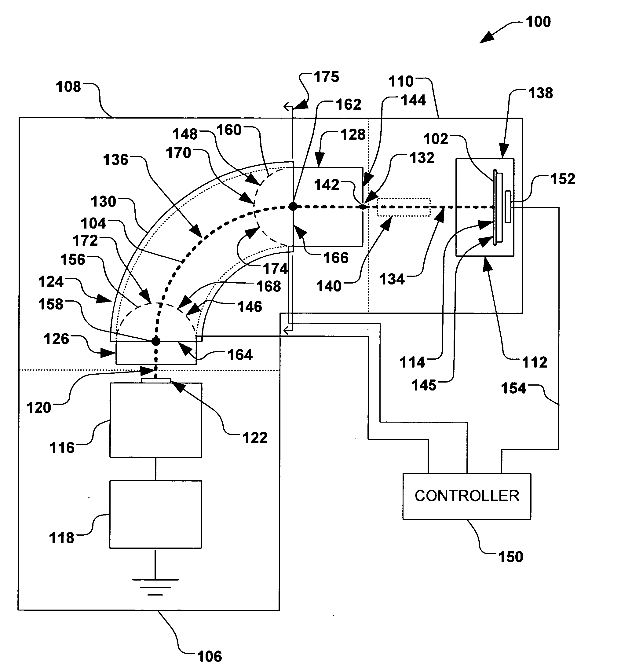
[0024]Referring now to the figures, in accordance with one exemplary aspect of the present invention, FIG. 1 illustrates an exemplary ion implantation system 100, wherein the ion implantation system is operable to scan a workp...


PUM


Abstract

An ion implantation apparatus, system, and method for controlling an ion beam, wherein a mass analyzer generally positioned between an ion source and an end station is configured to selectively control a path of a desired ion beam. The mass analyzer comprises one or more of an entrance pole mechanism positionable proximate to an entrance of the mass analyzer and an exit pole mechanism positionable proximate to an exit of the mass analyzer, wherein the position of the entrance pole mechanism and exit pole mechanism generally determines the path and focal point of the desired ion beam. A controller is configured to selectively position one or more of the entrance pole mechanism and exit pole mechanism, therein generally controlling the path of the desired ion beam at the exit of the mass analyzer, wherein the control may be based on one or more detected characteristics of the desired ion beam.

Description

FIELD OF THE INVENTION[0001]The present invention relates generally to ion implantation systems and methods for implanting ions into a workpiece, and more specifically to a system and method for tuning an ion beam.BACKGROUND OF THE INVENTION[0002]In the semiconductor industry, ion implantation systems are typically employed to dope a workpiece with impurities. In such systems, an ion source ionizes a desired dopant element, wherein ions are generally extracted from the ion source in the form of an undifferentiated ion beam. The undifferentiated ion beam is typically directed into a beamline assembly comprising a mass analysis apparatus or mass analyzer, wherein ions of a desired charge-to-mass ratio are selected using magnetic fields. Mass analyzers typically employ a mass analysis magnet (also called an AMU magnet) to create a dipole magnetic field, wherein various ions in an ion beam are deflected via magnetic deflection in an arcuate passageway that effectively separates ions of ...

Claims


Application Information

Patent Timeline
Patent Type & Authority Applications(United States)
IPC IPC(8): H01J37/317H01J49/20H01J49/30
CPCH01J37/026H01J2237/31701H01J37/21H01J37/304H01J37/3171H01J49/30H01J2237/024H01J2237/055H01J2237/057H01J2237/1502H01J2237/152H01J2237/2485H01J2237/3045H01J2237/30455H01J37/05
Inventor HUANG, YONGZHANG
Owner AXCELIS TECHNOLOGIES
Why Eureka
Try Eureka