Imaging method and image forming apparatus

Active Publication Date: 2008-03-20
RICOH KK
View PDF8 Cites 16 Cited by
  • Summary
  • Abstract
  • Description
  • Claims
  • Application Information

AI Technical Summary

Benefits of technology

[0021]Embodiments of the present invention are related to an imaging method for achieving higher image quality in forming an image by combining halftone processing using a linear base tone

Problems solved by technology

However, such an image forming apparatus has limited capacity to form multiple tones with recording liquid droplets in different dot sizes.
This leads to reduction of image quality due to problems such as uneven printing results and banding.
Even with the above-described apparatuses disclosed in Japanese Laid-Open Patent Application No. 2002-96455 and Japanese Registered Patent No. 3507415, the impact points tend to vary as the mask pattern becomes larger, and uneven printing results and banding may not be adequately prevented.
Thus

Method used


Image

  • Imaging method and image forming apparatus
  • Imaging method and image forming apparatus
  • Imaging method and image forming apparatus

Examples


Example

PREPARATION EXAMPLE 1

[0419]-Preparation of Dispersion of Polymer Microparticles Containing Copper Phthalocyanine Pigment-

[0420]To prepare a dispersion of polymer microparticles containing a copper phthalocyanine pigment, the air in a 1 L flask with a mechanical stirrer, a thermometer, a nitrogen gas inlet tube, a reflux tube, and a dropping funnel was replaced sufficiently with nitrogen gas; the 1 L flask was charged with 11.2 g of styrene, 2.8 g of acrylic acid, 12.0 g of lauryl methacrylate, 4.0 g of polyethylene glycol methacrylate, 4.0 g of styrene macromer (Toagosei Co., Ltd., brand name: AS-6), and 0.4 g of mercaptoethanol; and the temperature was raised to 65° C. Then, a mixed solution of 100.8 g styrene, 25.2 g of acrylic acid, 108.0 g of lauryl methacrylate, 36.0 g of polyethylene glycol methacrylate, 60.0 g of hydroxyethyl methacrylate, 36.0 g of styrene macromer (Toagosei Co., Ltd., brand name: AS-6), 3.6 g of mercaptoethanol, 2.4 g of azobisdimethylvaleronitrile, and 18....

Example

PREPARATION EXAMPLE 2

[0424]-Preparation of Dispersion of Polymer Microparticles Containing Dimethyl Quinacridone Pigment-

[0425]A polymer microparticle dispersion with magenta color was prepared in substantially the same manner as the preparation example 1, except that C. I. Pigment Red 122 was used instead of a copper phthalocyanine pigment.

[0426]The average particle diameter (D50%) of the polymer microparticles in the polymer microparticle dispersion was measured with a particle size distribution analyzer (Microtrac UPA, Nikkiso Co., Ltd.). The average particle diameter was 127 nm.

Example

PREPARATION EXAMPLE 3

[0427]-Preparation of Dispersion of Polymer Microparticles Containing Monoazo Yellow Pigment-

[0428]A polymer microparticle dispersion with a yellow color was prepared in substantially the same manner as the preparation example 1, except that C. I. Pigment Yellow 74 was used instead of a copper phthalocyanine pigment.

[0429]The average particle diameter (D50%) of the polymer microparticles in the polymer microparticle dispersion was measured with a particle size distribution analyzer (Microtrac UPA, Nikkiso Co., Ltd.). The average particle diameter was 76 nm.


PUM

PropertyMeasurementUnit
Pressureaaaaaaaaaa
Pressureaaaaaaaaaa
Pressureaaaaaaaaaa

Abstract

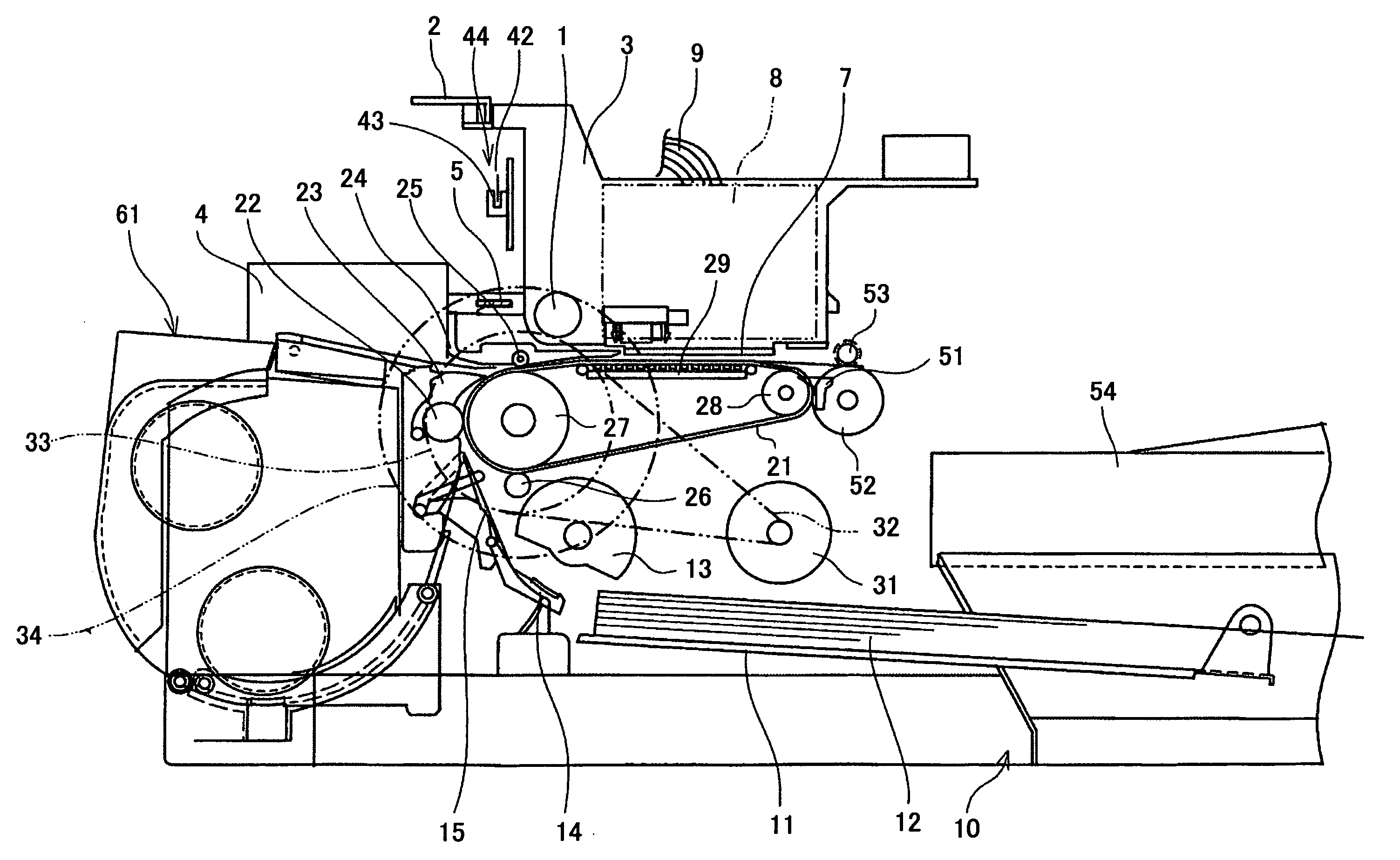
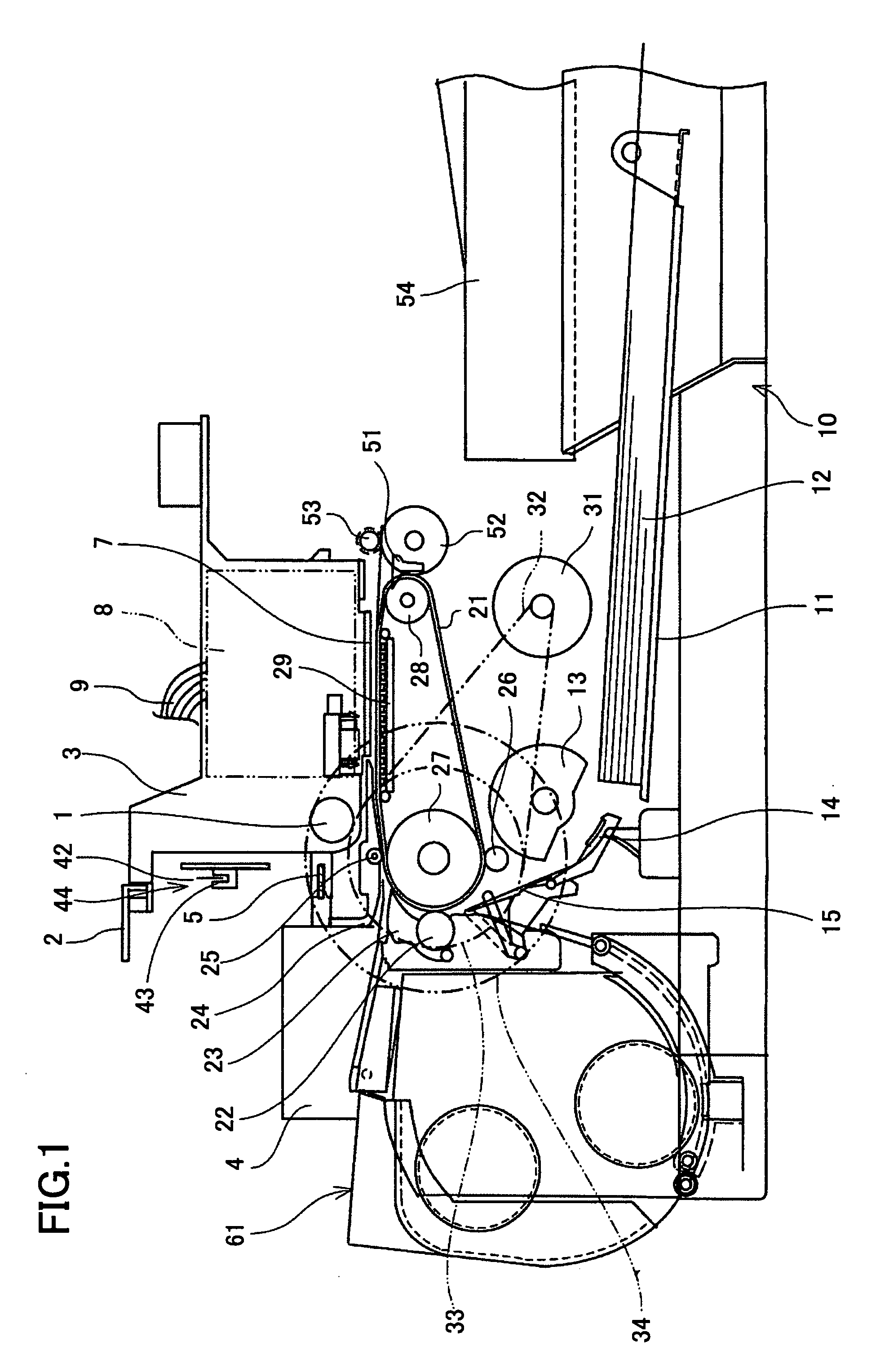
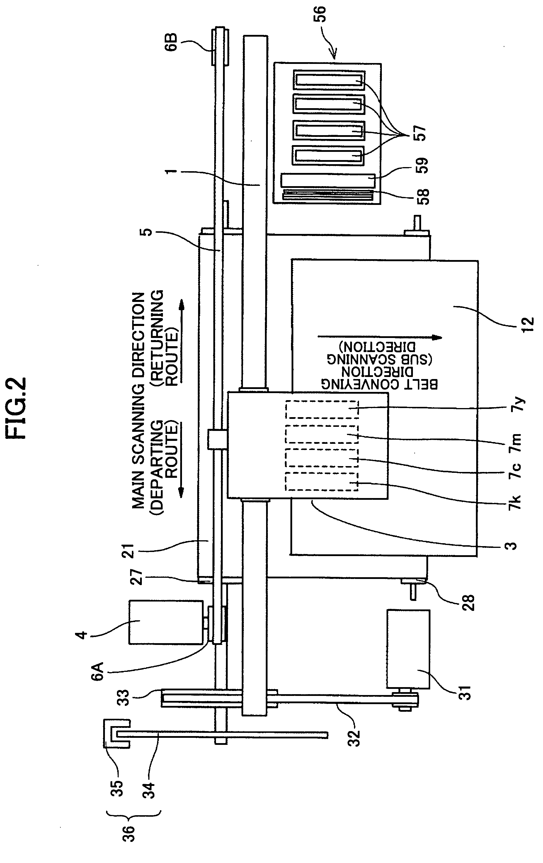
An imaging method is disclosed that is implemented in an image forming apparatus for forming a tone pattern on a recording medium by forming an arrangement of dots on the recording medium. The arrangement of dots is formed on the recording medium by jetting a recording liquid from a recording head while moving the recording head in a main scanning direction a plurality of times and intermittently conveying the recording medium in a sub-scanning direction that perpendicularly intersects the main scanning direction. The imaging method involves forming the arrangement of dots such that dots belonging to a first group that are consecutively aligned in a base tone direction and dots belonging to a second group that are consecutively aligned in the sub scanning direction are respectively formed in non-consecutive order on the recording medium.

Description

BACKGROUND OF THE INVENTION[0001]1. Field of the Invention[0002]The present invention relates to an imaging method for enabling high resolution image formation at high speed, an image forming apparatus that performs such an imaging method, and a computer-readable program that enables a computer to perform such imaging method.[0003]2. Description of the Related Art[0004]An inkjet recording apparatus is an image forming apparatus that uses one or more liquid jetting heads and may be used as a printer, a facsimile, a copier, or a multifunction copier having functions of a printer, facsimile, and copier, for example.[0005]The inkjet recording apparatus forms (i.e. records, prints) images by discharging ink (i.e. recording liquid) from its recording head and onto the surface of a recording medium such as a sheet of paper some other medium on which recording liquid may be applied.[0006]An image forming apparatus may be configured to form four different types (four tones) of dots, namely, ...

Claims


Application Information

Patent Timeline
IPC IPC(8): B41J29/38B41J2/01B41J2/175B41M5/00B41M5/50B41M5/52C09D11/00C09D11/322C09D11/324C09D11/326C09D11/328C09D11/38
CPCB41J2/2132B41J29/393B41J29/38
Inventor KIKUCHI, NAOKIKIMURA, TAKASHIHOSAKA, SHIGETOSHI
Owner RICOH KK
Why Eureka
Try Eureka