
Inspection method and apparatus, lithographic apparatus, lithographic processing cell and device manufacturing method

a technology of lithographic processing cell and manufacturing method, which is applied in the direction of material analysis, instruments, geological measurements, etc., can solve the problems of large amount of time, effort and apparatus, and the system does not work well for overlapping shapes

Active Publication Date: 2008-03-20
ASML NETHERLANDS BV
View PDF14 Cites 6 Cited by
  • Summary
  • Abstract
  • Description
  • Claims
  • Application Information

AI Technical Summary

Benefits of technology

[0011]It is desirable to provide a system that reduces the number of degrees of freedom of measurement points or parameters in a scatterometry object in order to provide a quick method of reconstructing the profile of a scatterometry object from its diffraction spectrum.
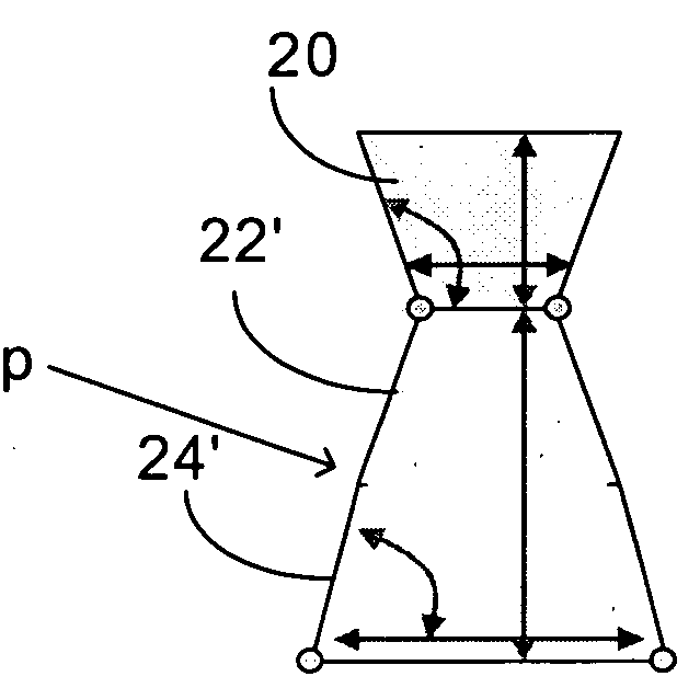
[0012]According to an embodiment of the invention, a method of reconstructing the shape of an object from a diffraction pattern resulting from radiation illuminating the object comprises detecting the diffraction pattern of radiation diffracted from the object; estimating the object shape; deriving a model diffraction pattern from the estimated shape; comparing the model diffraction pattern and the detected diffraction pattern; determining the actual object shape from the difference between the model diffraction pattern and the detected diffraction pattern, wherein the object shape is defined as a plurality of two- or three-dimensional shapes each with a plurality of variable geometric parameters; and linking together the variable geometric parameters of the different two- or three-dimensional shapes to give an approximation of an object shape defined by a two- or three-dimensional shape with a reduced number of variable parameters.

Problems solved by technology

However, this involves a large amount of time, effort and apparatus.
Clearly, the problem with this system is that the greater the number of parameters, the greater the number of iterations that the computer must carry out and the greater the processing power and time that is required.
Furthermore, this system does not work well for overlapping shapes (e.g. complex shapes that look like overlapping simpler shapes or a profile that has a coating) or multiple shapes in a single profile, as the lines joining the dots may easily join the wrong dots.
Another problem with this system is that each control point will have at least one (if not two or three) degree of freedom.

Method used


Image

  • Inspection method and apparatus, lithographic apparatus, lithographic processing cell and device manufacturing method
  • Inspection method and apparatus, lithographic apparatus, lithographic processing cell and device manufacturing method
  • Inspection method and apparatus, lithographic apparatus, lithographic processing cell and device manufacturing method

Examples


Embodiment Construction

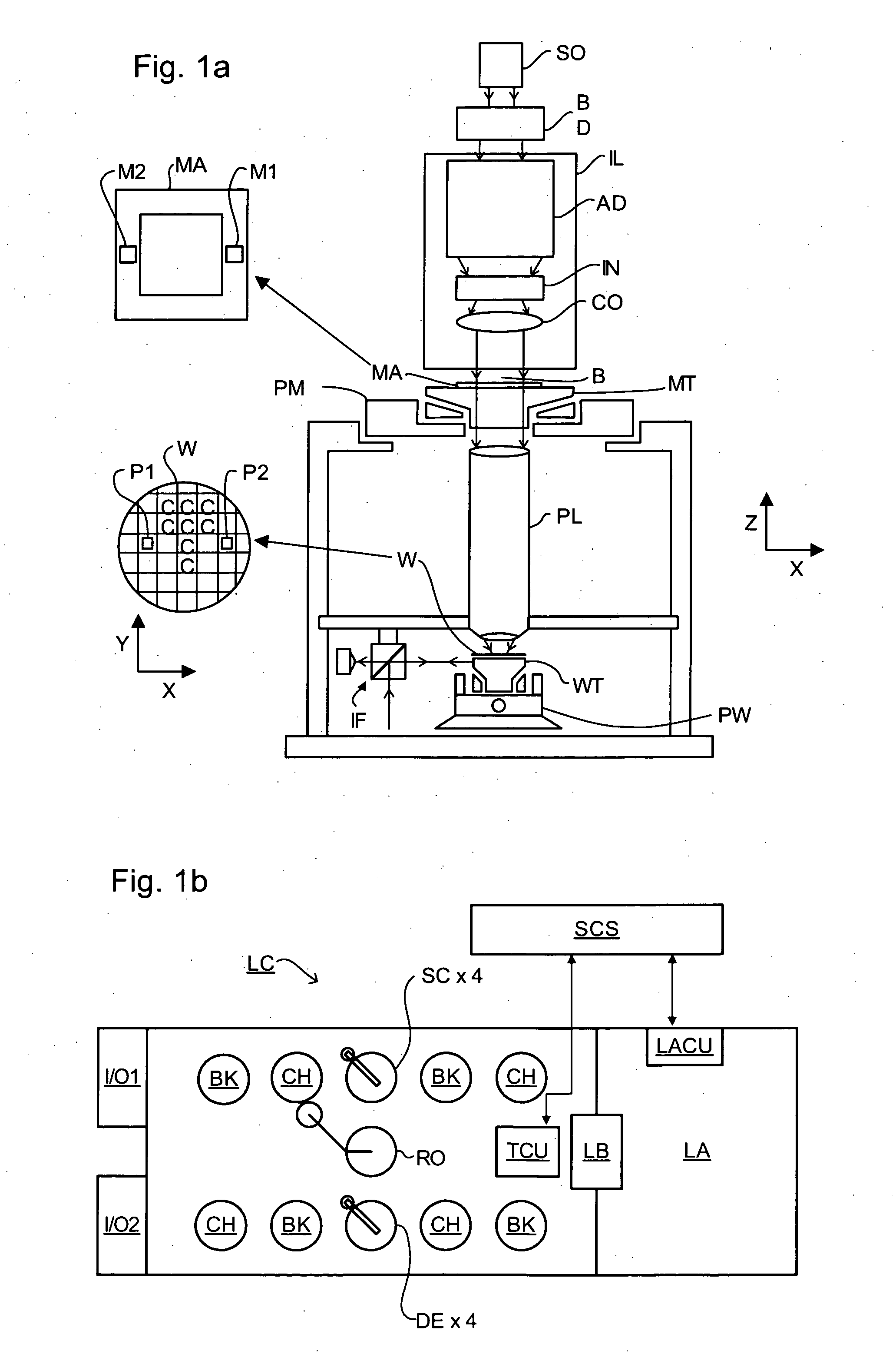
[0026]FIG. 1a schematically depicts a lithographic apparatus. The apparatus comprises an illumination system (illuminator) IL configured to condition a radiation beam B (e.g. UV radiation or EUV radiation). A support (e.g. a mask table) MT is configured to support a patterning device (e.g. a mask) MA and is connected to a first positioner PM configured to accurately position the patterning device in accordance with certain parameters. A substrate table (e.g. a wafer table) WT is configured to hold a substrate (e.g. a resist-coated wafer) W and is connected to a second positioner PW configured to accurately position the substrate in accordance with certain parameters. A projection system (e.g. a refractive projection lens system) PL is configured to project a pattern imparted to the radiation beam B by patterning device MA onto a target portion C (e.g. comprising one or more dies) of the substrate W.

[0027]The illumination system may include various types of optical components, such a...


PUM


Abstract

In target shape reconstruction, in order to determine efficiently and quickly the profile of complex targets on a substrate, the various degrees of freedom or variable parameters of the various shapes of which a single profile is made up can be reduced by linking together the variable parameters using simple formulae or by approximating the shape of the overall profile such that it takes in to account the various shapes making up that profile. Fewer parameters gives rise to fewer iterations of calculations on those parameters, which increases the speed of profile reconstruction.

Description

BACKGROUND OF THE INVENTION[0001]1. Field of the Invention[0002]The present invention relates to methods of inspection usable, for example, in the manufacture of devices by lithographic techniques and to methods of manufacturing devices using lithographic techniques.[0003]2. Description of the Related Art[0004]A lithographic apparatus is a machine that applies a desired pattern onto a substrate, usually onto a target portion of the substrate. A lithographic apparatus can be used, for example, in the manufacture of integrated circuits (ICs). In that instance, a patterning device, which is alternatively referred to as a mask or a reticle, may be used to generate a circuit pattern to be formed on an individual layer of the IC. This pattern can be transferred onto a target portion (e.g. comprising part of, one, or several dies) on a substrate (e.g. a silicon wafer). Transfer of the pattern is typically via imaging onto a layer of radiation-sensitive material (resist) provided on the sub...

Claims


Application Information

Patent Timeline
IPC IPC(8): G01B11/24
CPCG03F7/70625
Inventor KIERS, ANTOINE GASTON MARIENAUMOSKI, GOCE
Owner ASML NETHERLANDS BV
Learn More