Traveling wave amplifier with distributed regenerative feedback between drain-to-drain transmission lines and gate-to-gate transmission lines for enhanced high frequency bandwidth

a technology of regenerative feedback and transmission lines, which is applied in the direction of amplifiers with transit-time effects, amplifiers with coupling networks, and amplifiers with semiconductor devices/discharge tubes, etc., can solve the problems of increasing the device count by a factor of b>2, requiring a more complicated bias network, and difficult to stabilize, so as to achieve enhanced bandwidth and enhanced bandwidth , the effect of increasing the is21i bandwidth

Inactive Publication Date: 2008-03-27
MORDARSKI WILLIAM
View PDF2 Cites 4 Cited by
  • Summary
  • Abstract
  • Description
  • Claims
  • Application Information

AI Technical Summary

Benefits of technology

[0002]The object of the present invention is to provide enhanced, stable, bandwidth for a TWA amplifier topology with minimal number of devices in a circuit that is simple to fabricate for both hybrid and monolithic realizations.
[0003]Referring to FIG. 3, the enhanced bandwidth is achieved by designing the drain-to-drain and gate-to-gate transmission lines as coupled pairs, thereby coupling some energy back to the input from the output. The result is a small amount of distributed regenerative feedback (DRF) which provides a controlled degree of high frequency peaking. When optimized for flat gain, the frequency slope and phase of the fee

Problems solved by technology

But this practice also increases the device count by a factor of 2, requ

Method used


Image

  • Traveling wave amplifier with distributed regenerative feedback between drain-to-drain transmission lines and gate-to-gate transmission lines for enhanced high frequency bandwidth
  • Traveling wave amplifier with distributed regenerative feedback between drain-to-drain transmission lines and gate-to-gate transmission lines for enhanced high frequency bandwidth
  • Traveling wave amplifier with distributed regenerative feedback between drain-to-drain transmission lines and gate-to-gate transmission lines for enhanced high frequency bandwidth

Examples


Embodiment Construction

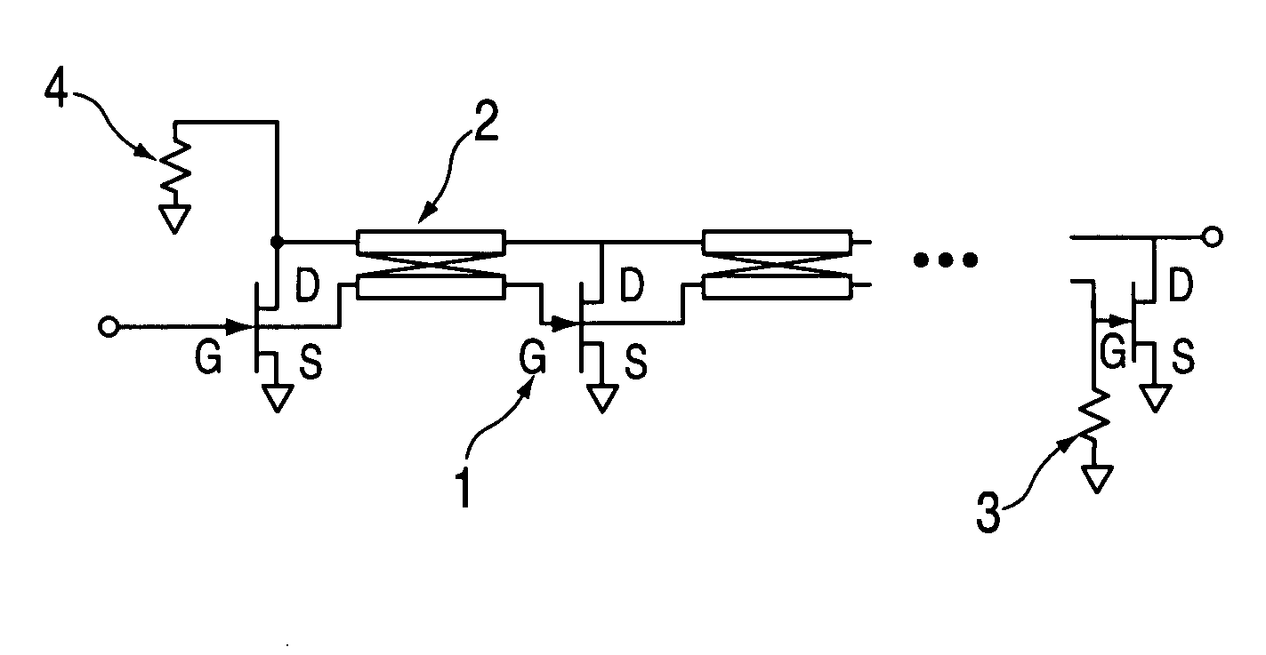
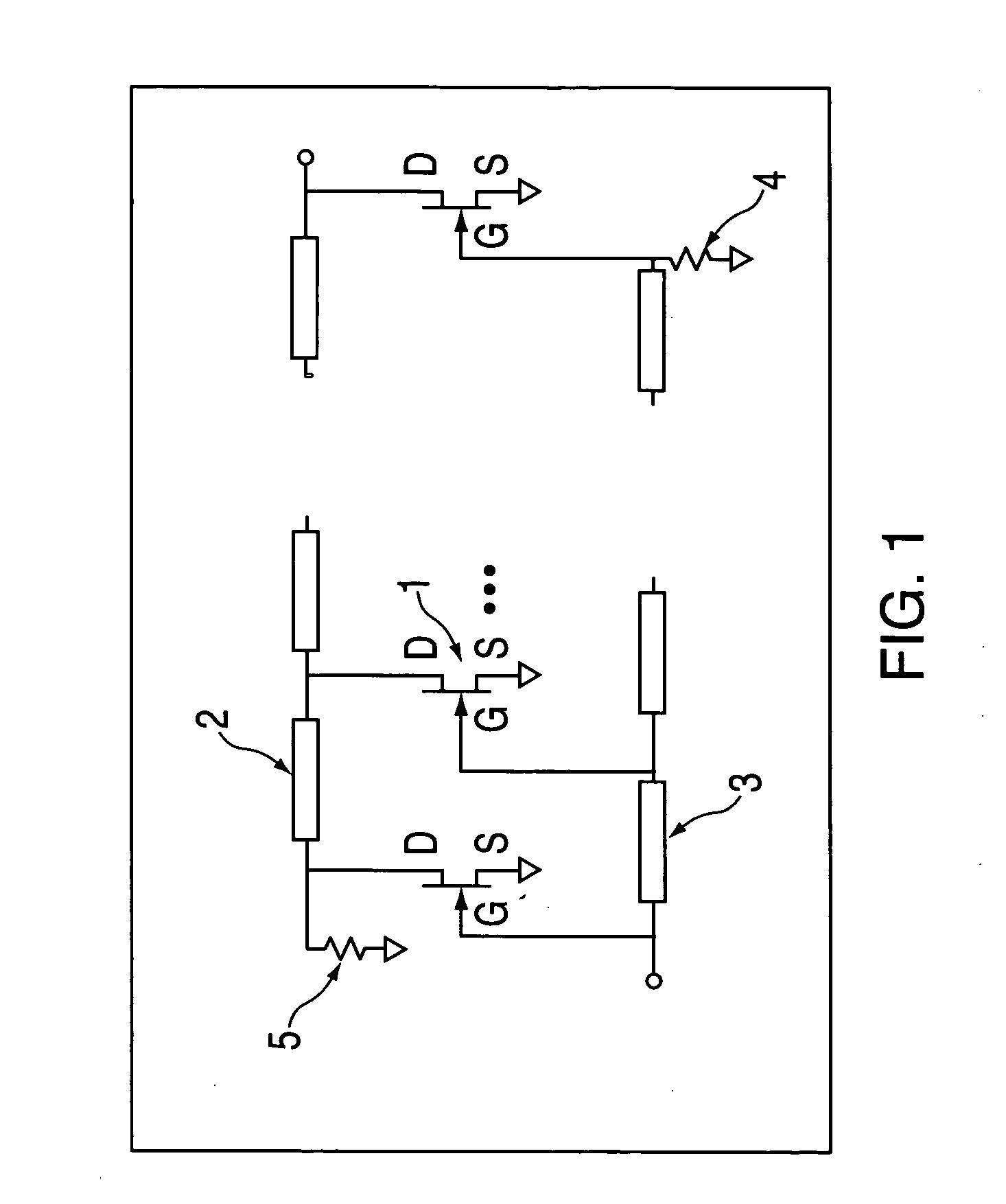
[0014]The prior art traveling wave amplifiers and Cascode traveling wave amplifiers are illustrated schematically in FIGS. 1 and 2. As explained in the Background of the Invention section above, these configurations suffer from defects that are solved by the present invention.

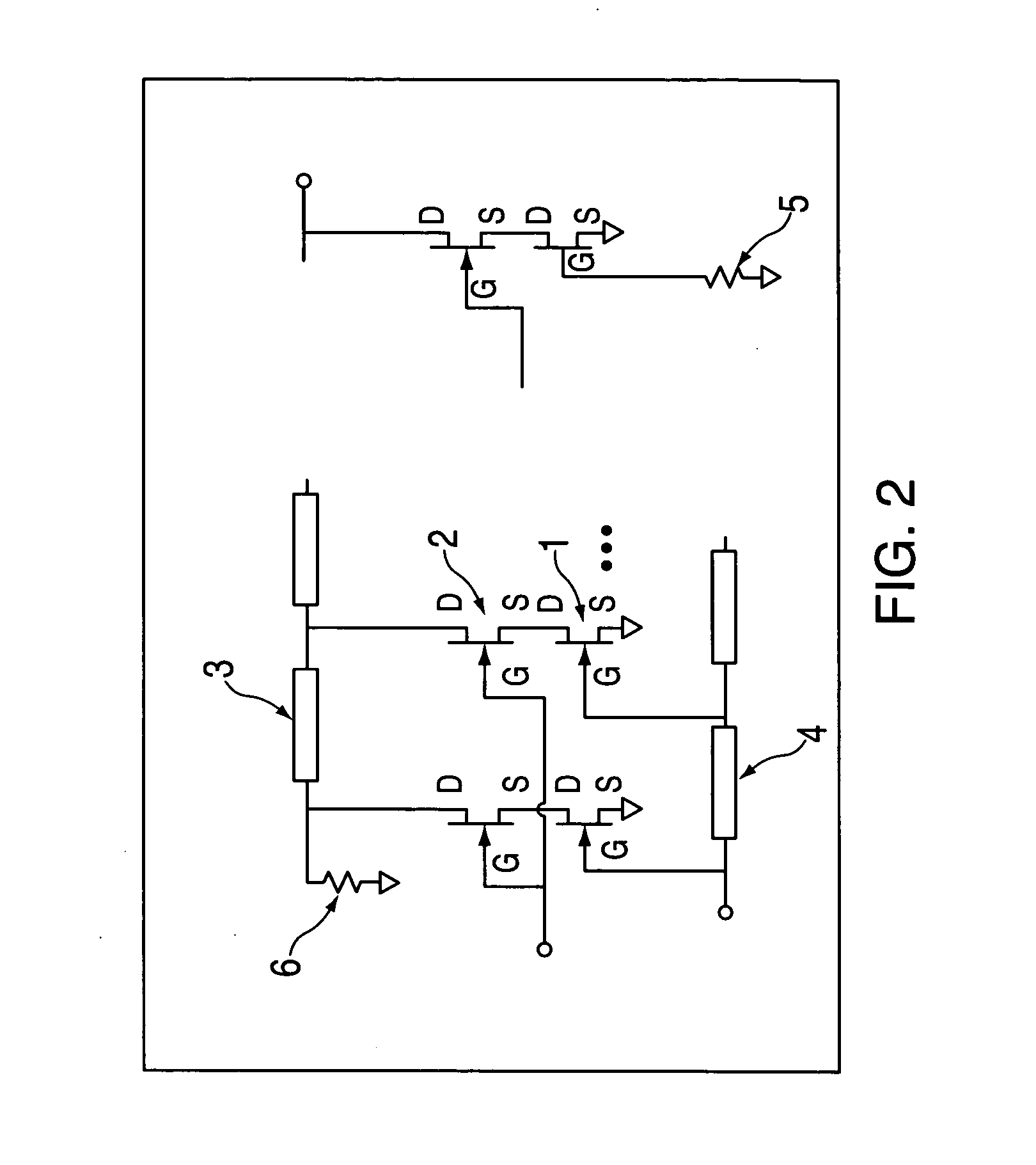
[0015]Referring to FIG. 3, the amplifier circuit is shown to include a plurality of semiconductor amplifier devices (1) each having an input electrode or gate (g) and output electrode or drain (d), a plurality of coupled transmission line pairs (2), and input and output termination networks (3) and (4). In the preferred embodiment, illustrated in FIG. 4, there are 2 FET devices, (10), (12), and a coupled transmission line pair (14) connected between the FET gate terminals (11) and drain terminals (13), in keeping with the object of wide bandwidth with low device count. In operation, a signal is fed to the input electrode of (10), and subsequently to the input electrode of the next semiconductor, (12), through t...


PUM


Abstract

An improved traveling wave amplifier is disclosed. The improvements to the traveling wave amplifier disclosed include designing the drain-to-drain and gate-to-gate transmission lines as coupled pairs thereby coupling energy back to the input from the output. The result. is increased bandwidth without an increase in device count or resorting to a cascade configuration.

Description

BACKGROUND OF THE INVENTION[0001]The present invention is directed to an improvement of the Traveling Wave Amplifier (TWA) (a / k / a Distributed Amplifier) shown in FIG. 1. Typically there are several FET devices (1) where the gates and drains of the FETs are connected with transmission lines, (3) and (2) respectively. The gate-to-gate transmission lines are designed to cancel reflections due to the capacitances of the FET gates, and incrementally absorb the energy from the input signal. Similarly, the drain-to-drain transmission lines are designed to cancel reflections due to capacitances of the FET drains and also to sum the amplified signal with the correct delay from each FET. The result, for a well-designed amplifier, is flat gain response and low input and output reflection over a wide band. Termination networks (4) and (5) provide low-frequency match at the input and output respectively. The bandwidth of the amplifier is determined by the capacitances of each individual FET as w...

Claims


Application Information

Patent Timeline
IPC IPC(8): H03F3/60H03F3/68
CPCH03F3/605H03F3/58
Inventor MORDARSKI, WILLIAM
Owner MORDARSKI WILLIAM
Why Eureka
Try Eureka