Antenna apparatus

a technology of antenna apparatus and antenna body, which is applied in the direction of antenna details, antenna earthings, antennas, etc., can solve the problems of increasing the manufacturing cost increasing the overall weight of the antenna apparatus, so as to achieve the effect of constant distance and easy manufacture of the antenna apparatus

Active Publication Date: 2008-03-27
MITSUMI ELECTRIC CO LTD
View PDF4 Cites 23 Cited by
  • Summary
  • Abstract
  • Description
  • Claims
  • Application Information

AI Technical Summary

Benefits of technology

[0018]Accordingly, an object of the invention is to provide an antenna apparatus having a small size, light weight, a low manufacturing cost, and sufficient capacitance.
[0019]Another object of the invention is to provide an antenna apparatus capable of preventing a variation in antenna resonance frequency and obtaining stable frequency characteristics.

Problems solved by technology

However, the high dielectric material, such as ceramic, is heavy and expensive.
Therefore, as described in Patent Documents 1, 3 and 4, when the high dielectric material, such as ceramic, is mounted on a small planar antenna apparatus, the overall weight of the antenna apparatus increases, and the manufacturing costs thereof also increase.
As a result, the planar antenna apparatus (the metal plate patch antenna) disclosed in Patent Document 2 has problems in that the antenna resonance frequency varies and stable frequency characteristics are not obtained.
However, in this structure, it is necessary to increase the areas of the electrodes (lands) in order to increase the capacitance value and improve the effect of shortening a wavelength, which results in an increase in the size of the substrate.

Method used


Image

  • Antenna apparatus
  • Antenna apparatus
  • Antenna apparatus

Examples


first embodiment

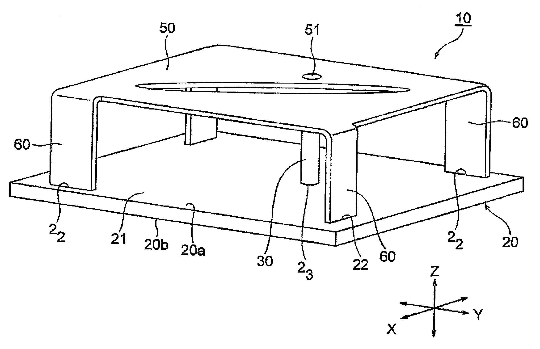
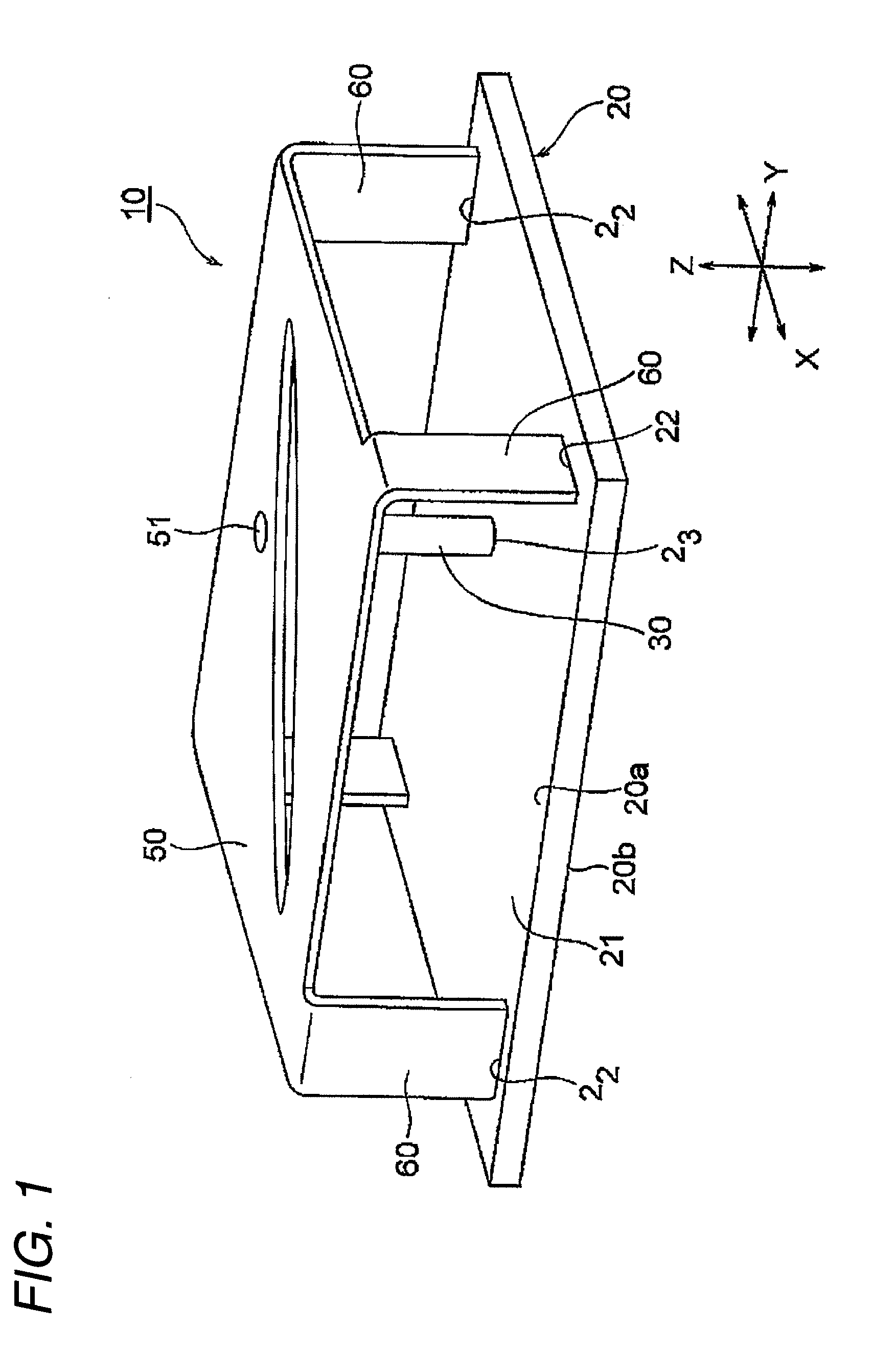
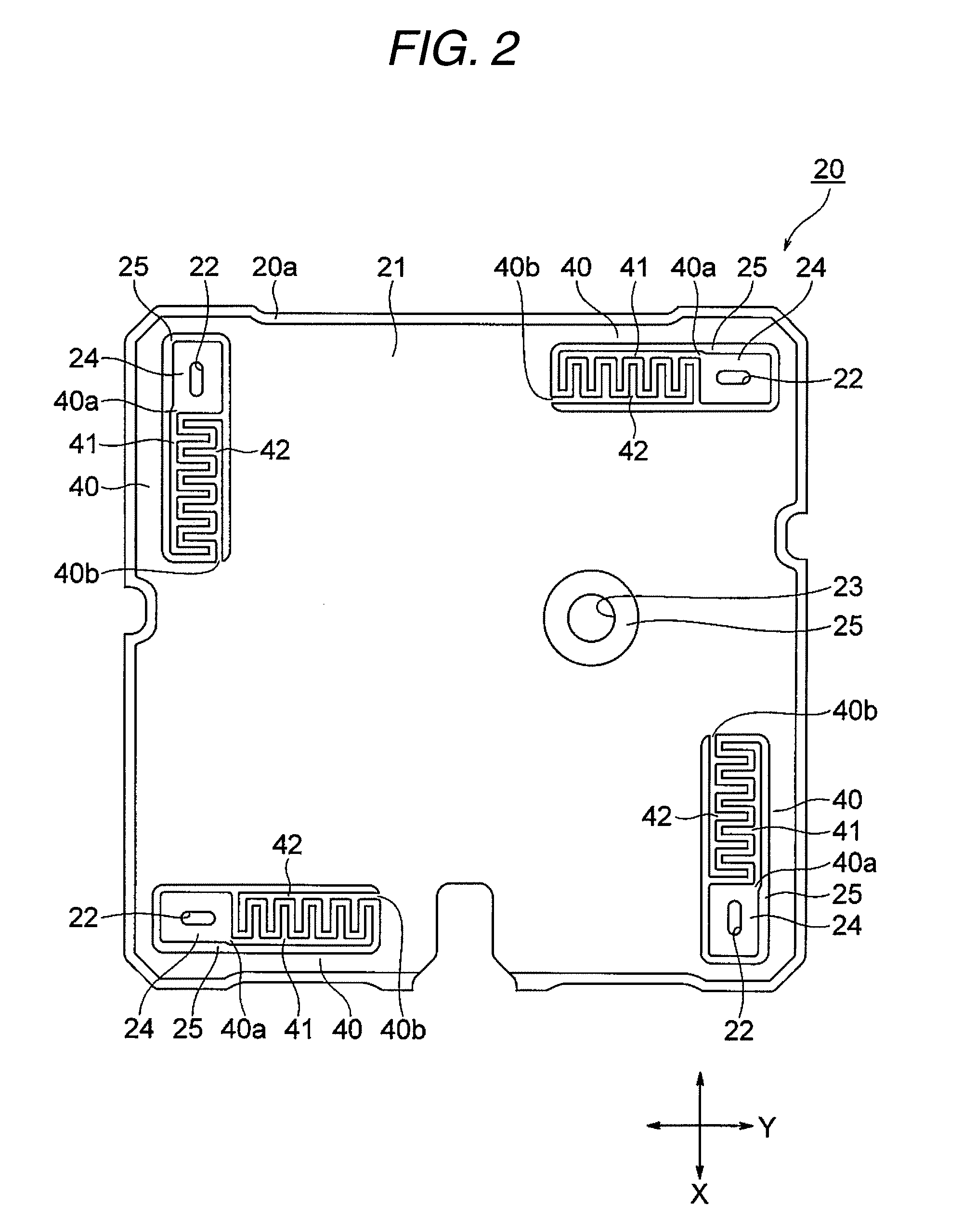
[0087]An antenna apparatus 10 according to a first embodiment of the invention will be described with reference to FIGS. 1 and 2. FIG. 1 is a perspective view illustrating the antenna apparatus 10. FIG. 2 is a top view illustrating a circuit board 20 used for the antenna apparatus 10 shown in FIG. 1, and FIG. 3 is a bottom view illustrating the circuit board 20. In FIGS. 1 to 3, forward and backward directions (a depth direction) indicate an X-axis direction, a horizontal direction (a width direction) indicates a Y-axis direction, and a vertical direction (a height direction or a thickness direction) indicates a Z-axis direction. The antenna apparatus 10 shown in FIGS. 1 to 3 is a GPS antenna for receiving GPS signals from GPS satellites.

[0088]As shown in FIG. 1, the antenna apparatus 10 includes the circuit board 20 having a conductor layer 21, such as a copper-clad film, on an upper surface (the main surface) 20a. The conductor layer 21 serves as a ground conductor. The circuit bo...

second embodiment

[0111]FIGS. 4 and 5 show a circuit board 20A that is used for an antenna apparatus according to a second embodiment of the invention. FIG. 4 is an enlarged top view (a plan view) illustrating a corner of an upper surface 20a of the circuit board 20A, and FIG. 5 is an enlarged bottom view illustrating a corner of a lower surface 20b of the circuit board 20A.

[0112]The circuit board 20A shown in FIGS. 4 and 5 has the comb-shaped capacitor patterns 40 on only the lower surface 20b, unlike the circuit board 20. In FIGS. 4 and 5, components having the same functions as those shown in FIGS. 2 and 3 are denoted by the same reference numerals.

[0113]As shown in FIG. 5, a pair of comb-shaped capacitor patterns 40 are provided so as to be connected to both ends of each conductive portion 26 on the lower surface (rear surface) 20b of the circuit board 20A. Each of the comb-shaped capacitor patterns 40 is arranged such that one end 40a thereof is connected to the conductive portion 26 and the oth...

third embodiment

[0117]Hereinafter, a third embodiment of the invention will be described with reference to FIGS. 6 to 9. However, the scope of the invention is not limited thereto.

[0118]FIG. 6 is a perspective view illustrating an antenna apparatus 101 according to the third embodiment of the invention. FIG. 7 is a bottom view illustrating the antenna apparatus 101 shown in FIG. 6. FIG. 8 is an enlarged view illustrating a portion of an upper surface of a dielectric substrate of the antenna apparatus shown in FIG. 6, and FIG. 9 is an enlarged view illustrating a portion of a lower surface of the dielectric substrate of the antenna apparatus shown in FIG. 6.

[0119]As shown in FIGS. 6 and 7, the antenna apparatus 101 includes a dielectric substrate 102 having conductor layers 121, such as copper-clad films, on both surfaces. The dielectric substrate 102 is formed in a rectangular shape, and four clearance holes 122 are provided in the vicinities of four corners of the dielectric substrate 102. In addi...


PUM


Abstract

An antenna apparatus includes: a circuit board that has a main surface and a rear surface opposite to each other; an antenna element that is formed of a metal plate and is arranged at a predetermined distance from the main surface of the circuit board; a plurality of legs that extend from the antenna element toward the circuit board; a ground conductor that is formed on the main surface or the rear surface of the circuit board; a feeding pin that supplies power from the circuit board to the antenna element; and a plurality of comb-shaped capacitor patterns that are formed on one of or both the main surface and the rear surface of the circuit board and are electrically connected between the plurality of legs and the ground conductor.

Description

BACKGROUND OF THE INVENTION[0001]1. Technical Field of the Invention[0002]The present invention relates to an antenna apparatus, and more particularly, to a small planar antenna apparatus used as a global positioning system (GPS) antenna.[0003]2. Related Art[0004]As known in this technical field, a GPS (global positioning system) measures the position of an object using a satellite. The GPS receives radio waves (GPS signals) from four or more satellites among 24 satellites that orbit the earth, measures the positional relationship between a moving object and the satellites and a time error therebetween using the received radio waves, and accurately calculates the position and altitude of the moving object on the map using triangulation.[0005]In recent years, the GPS has come into widespread use for car navigation systems for detecting the position of a traveling vehicle. The car navigation system includes a GPS antenna for receiving GPS signals, a processing unit that processes the ...

Claims


Application Information

Patent Timeline
Patent Type & Authority Applications(United States)
IPC IPC(8): H01Q9/04H01Q1/38
CPCH01Q9/0442H01Q9/0421
Inventor NORO, JUNICHIYONEYA, AKIRAFUKAE, ISAOSHINKAWA, TOMOHIROSAITO, KAZUNARIMIYOSHI, AKIRAKOHNO, SATOSHI
Owner MITSUMI ELECTRIC CO LTD
Why Eureka
Try Eureka