Phaser-actuated continuously variable valve actuation system with lost motion capability

a technology of continuously variable valves and phasers, applied in the direction of valve arrangements, machines/engines, mechanical equipment, etc., can solve the problems of requiring significantly more power than a conventional fixed-lift and fixed-duration valvetrain system, and the cost of a conventional engine itself, and achieve the effect of improving the performance of both spark-ignited and compression-ignited engines

Inactive Publication Date: 2008-04-03
DELPHI TECH INC
View PDF4 Cites 28 Cited by
  • Summary
  • Abstract
  • Description
  • Claims
  • Application Information

AI Technical Summary

Benefits of technology

[0015]Briefly described, a system in accordance with the invention for continuously varying actuation of a valve in a valvetrain in an internal combustion engine comprises a first-cam lobe for opening the valve, the first cam lobe having a first base circle portion and a first working portion; a second cam lobe for closing the valve, the second cam lobe having a second base circle portion and a second working portion; and an oscillating rocker arm having first, second, and third working elements and being disposed among and continuously engaging each of the first cam lobe in contact with the first working element, the second cam lobe in contact with the second working element, and the valvetrain in contact with the third working element, with the aid of a lost motion spring. The cams are disposed on first and second camshafts that are geared together. The first (opening) camshaft gear is driven by the engine crankshaft and thus is phase-invariant. The second (closing) camshaft gear is rotationally mounted on the second camshaft and supports the stator of a camshaft phaser. The phaser rotor is mounted to the second camshaft. Varying the rotor position varies the phase of the second cam lobe and thus varies lift and closing timing of the combustion valve. The system is useful in improving the performance of both spark-ignited and compression-ignited engines.

Problems solved by technology

One of the drawbacks inhibiting the introduction of a gasoline or Diesel Homogeneous Charge Compression Ignited (HCCI) engine in production has been the lack of a simple, cost effective and energy efficient Variable Valvetrain Actuation (VVA) system to vary intake events.
Many electro-hydraulic and electromechanical (magnetic) “camless” VVA systems have been proposed for gasoline or Diesel HCCI engines, but while these systems may consume less or equivalent actuation power at low engine speeds, they typically require significantly more power than a conventional fixed-lift and fixed-duration valvetrain system to actuate at mid and upper engine speeds.
Moreover, the cost of these “camless” systems can approach the cost of an entire conventional engine itself.
As the cost of petroleum continues to rise from increased global demands and limited supplies, the fuel economy benefits of internal combustion engines will become a central issue in their design, manufacture, and use at the consumer level.
A shortcoming of the disclosed system is that the timing of valve opening and valve closing cannot be independently controlled; e.g., valve opening timing cannot be held constant while varying valve closing timing.
Also, valve lift cannot be controlled independently of valve opening and valve closing.

Method used


Image

  • Phaser-actuated continuously variable valve actuation system with lost motion capability
  • Phaser-actuated continuously variable valve actuation system with lost motion capability
  • Phaser-actuated continuously variable valve actuation system with lost motion capability

Examples


Embodiment Construction

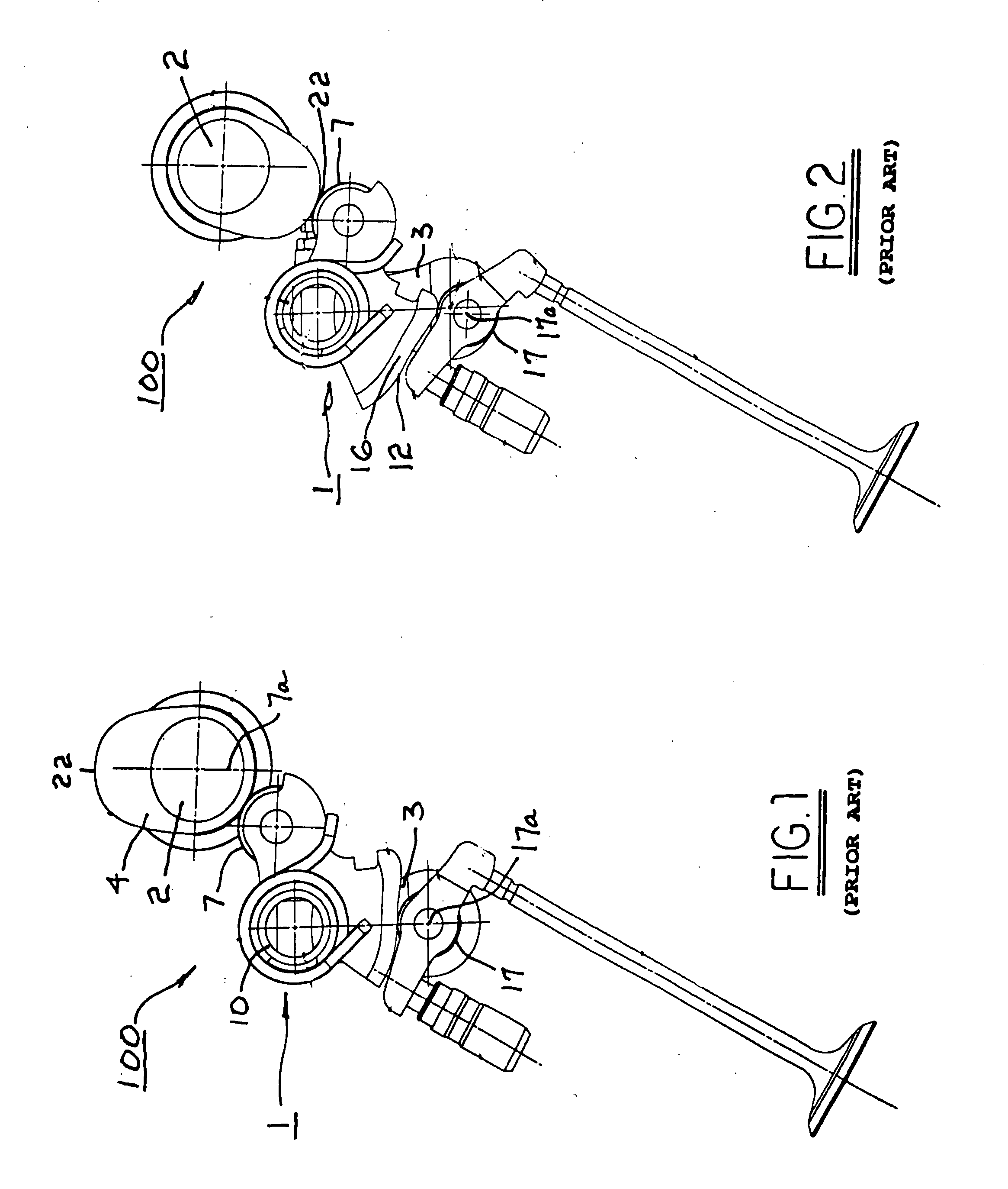
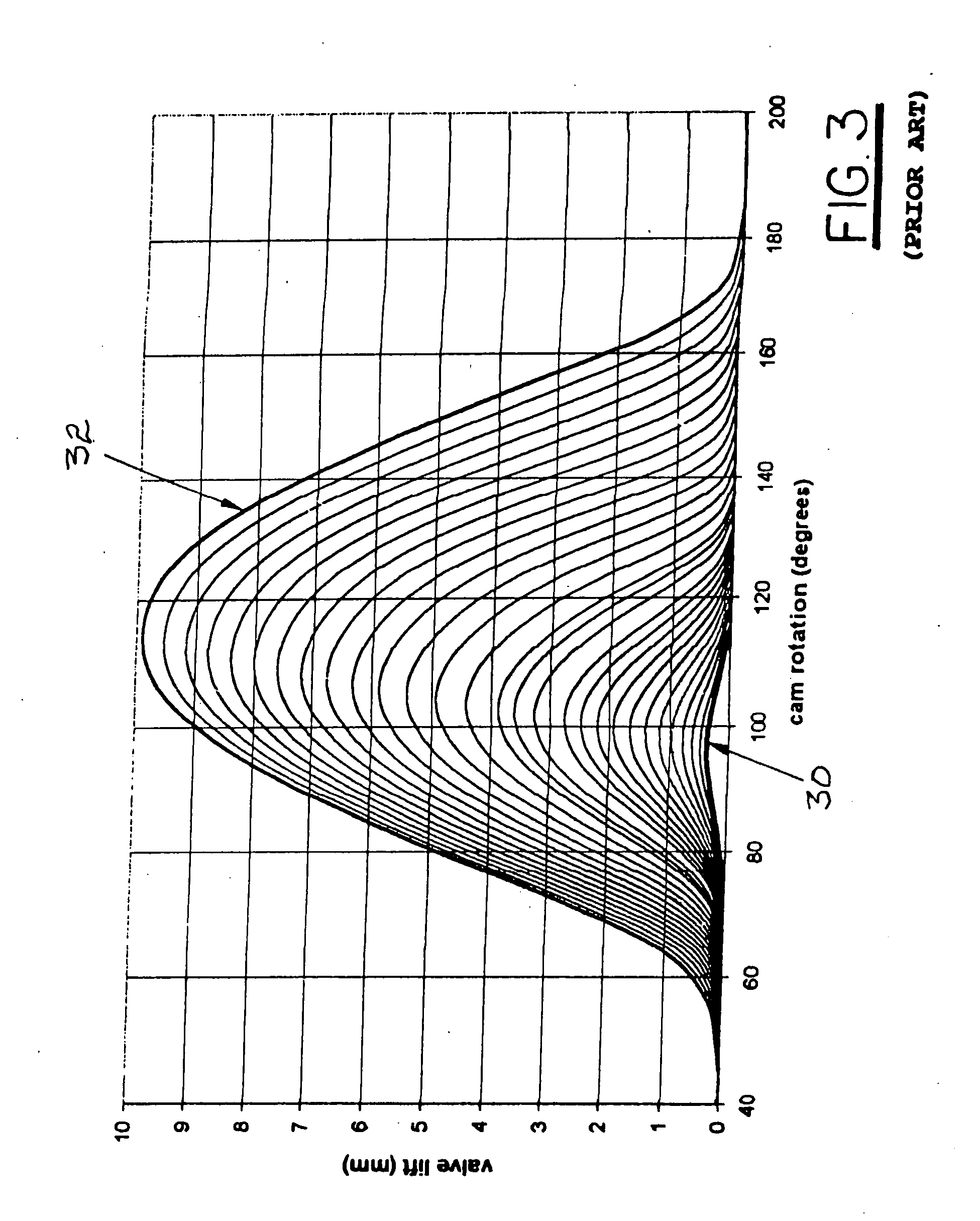
[0033]The benefits and advantages of a VVA system in accordance with the present invention may be better appreciated by first considering a relevant prior art WA system for varying valve opening timing, valve closing timing, and valve lift.

[0034]Referring to FIGS. 1 through 3, a prior art VVA valvetrain system 100, substantially as disclosed in Published United States Patent Application No. 2007 / 0125329, includes a control shaft assembly 1 shown at the intake valve camshaft 2 of an inline 4-cylinder engine which may be spark-ignited or compression-ignited. Control shaft assembly 1 manages an engine's gas exchange process by varying the angular position of the control shaft assembly. In FIGS. 1 and 2, system 100 is shown in its full engine load position. In FIG. 1, the input camshaft is on its base circle portion, and in FIG. 2, the input camshaft is at its peak lift point. High lift events with full duration are produced by the system whenever the control shaft arms 3 are in the nea...


PUM


Abstract

A system for continuously varying actuation of a valve in an internal combustion engine including a first cam for opening the valve, a second cam for closing the valve, and an oscillating rocker arm continuously engaging each of the first cam, the second cam, and the valvetrain, with the aid of a lost motion spring. The cams are disposed on first and second camshafts that are geared together. The first camshaft gear is driven by the engine crankshaft and thus is phase-invariant. The second camshaft gear is rotationally mounted on the second camshaft and supports the stator of a camshaft phaser. The phaser rotor is mounted to the second camshaft. Varying the rotor position varies the phase of the second cam and thus varies lift and closing timing of the valve. The system is useful in improving the performance of both spark-ignited and compression-ignited engines.

Description

CROSS-REFERENCE TO RELATED APPLICATION[0001]This present invention relates to provisional application Ser. No. 60 / 847,784, filed on Sep. 28, 2006.RELATIONSHIP TO GOVERNMENT CONTRACTS[0002]The present invention was supported in part by a U.S. Government Contract, No. FC26-05NT42483. The United States Government may have rights in the present invention.TECHNICAL FIELD[0003]The present invention relates to the actuation of combustion valves in internal combustion engines; more particularly, to mechanisms for variable actuation of combustion valves; and most particularly, to a system for continuously variable valve actuation.BACKGROUND OF THE INVENTION[0004]One of the drawbacks inhibiting the introduction of a gasoline or Diesel Homogeneous Charge Compression Ignited (HCCI) engine in production has been the lack of a simple, cost effective and energy efficient Variable Valvetrain Actuation (VVA) system to vary intake events. Many electro-hydraulic and electromechanical (magnetic) “camle...

Claims


Application Information

Patent Timeline
Patent Type & Authority Applications(United States)
IPC IPC(8): F01L1/34
CPCF01L13/0021F01L2001/0476F01L13/0063F01L13/0047F01L2001/0478
Inventor KNAUF, MICHAEL B.ROHE, JEFFREY D.LEE, JONGMINSUH, EDWARD S.FERNANDEZ, HERMES A.SOCHA, JOHN R.
Owner DELPHI TECH INC
Why Eureka
Try Eureka