

Adsorption module and method of manufacturing the same
a technology of adsorption module and a manufacturing method, which is applied in the direction of refrigeration components, indirect heat exchangers, lighting and heating apparatus, etc., can solve problems such as affecting cooling efficiency, and achieve the effect of reducing the number of steps
- Summary
- Abstract
- Description
- Claims
- Application Information
AI Technical Summary
Benefits of technology
Problems solved by technology
Method used
Image

Examples
first embodiment
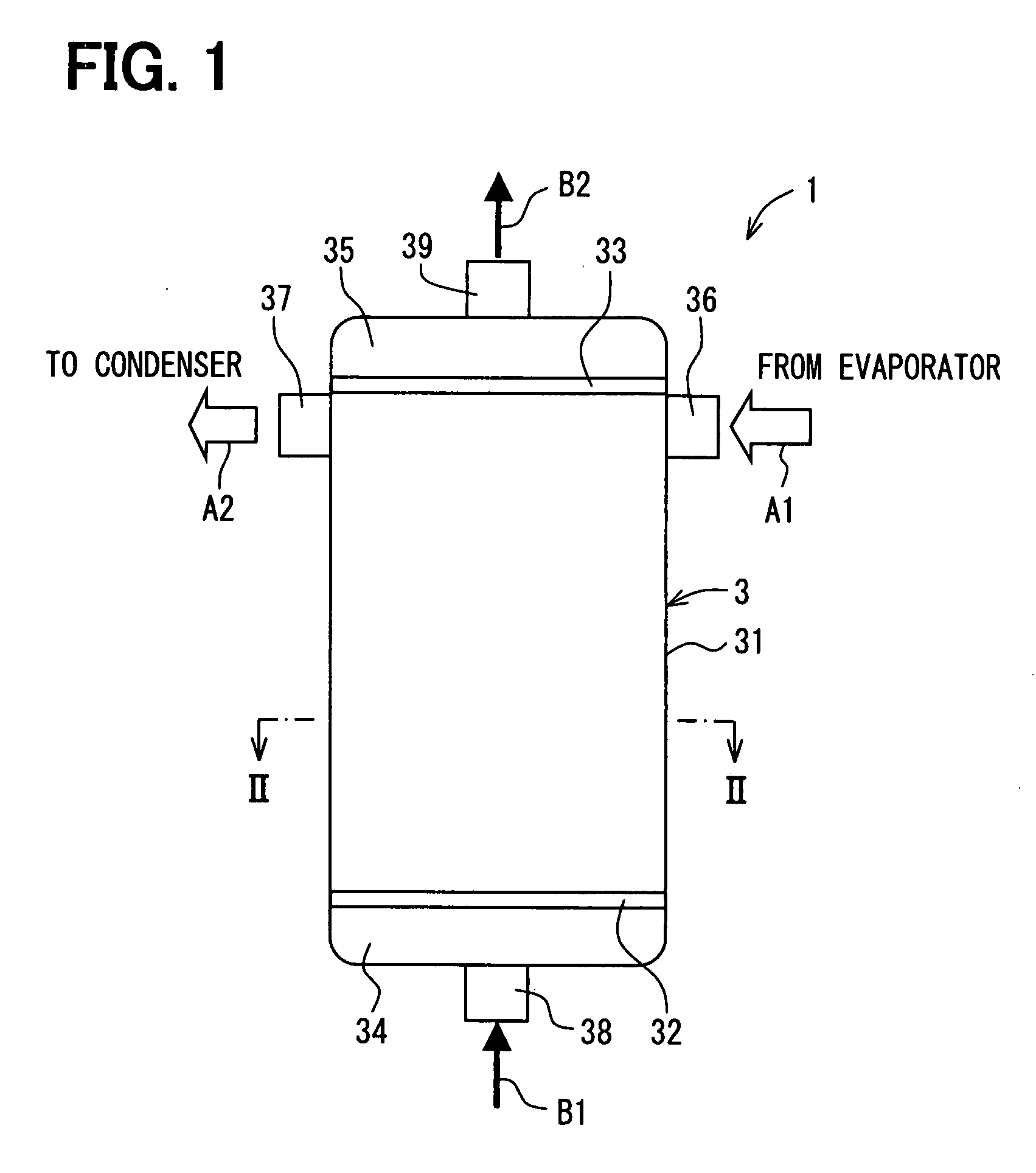
[0051]A first embodiment of the present invention will now be described. As shown i n FIGS. 1 to 3, an adsorption module 1 is for example employed in an adsorption refrigerating apparatus that provides a refrigerating capability due to latent heat of evaporation caused by evaporation of refrigerant using an adsorption activity of adsorbent contained in the adsorption module 1. The adsorption module 1 can be employed in an air conditioning apparatus for a vehicle, for example.
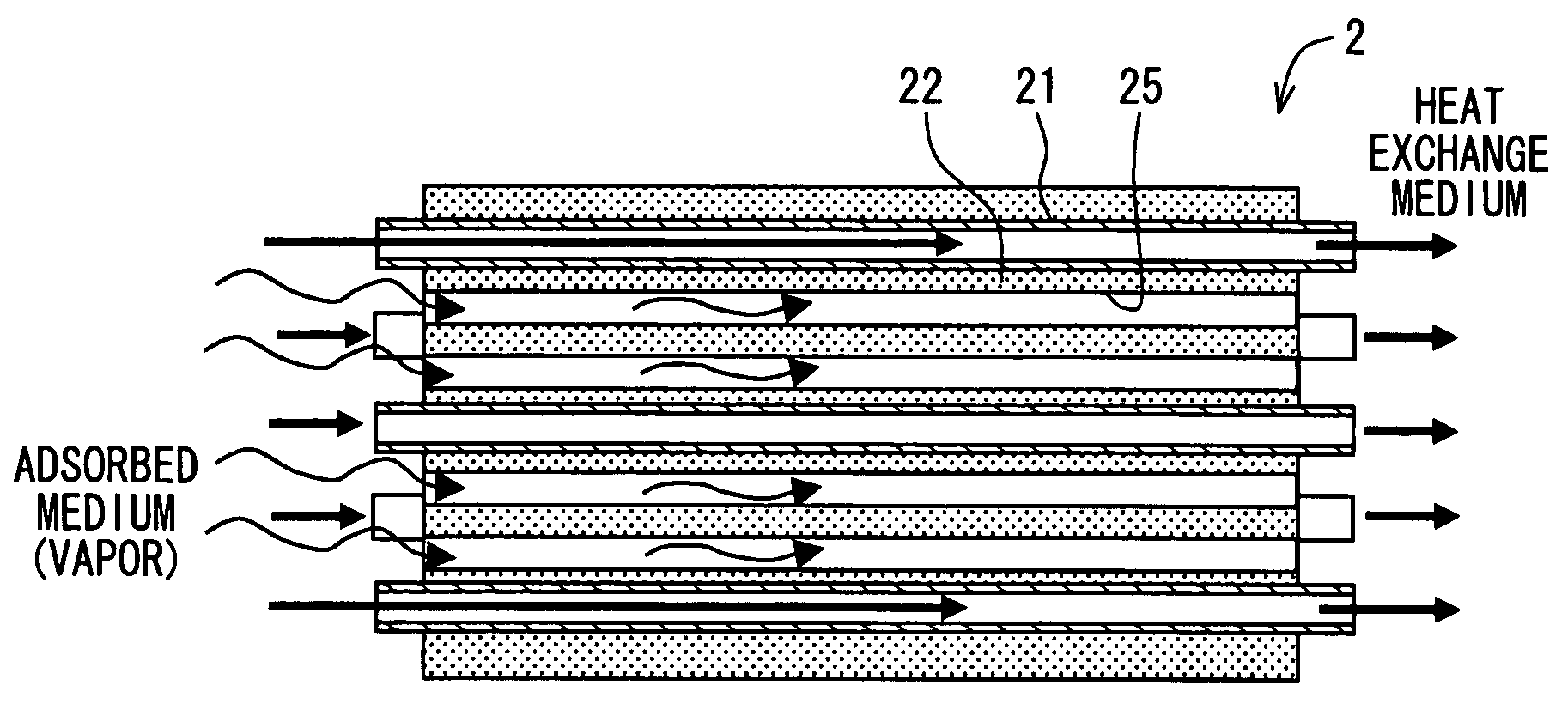
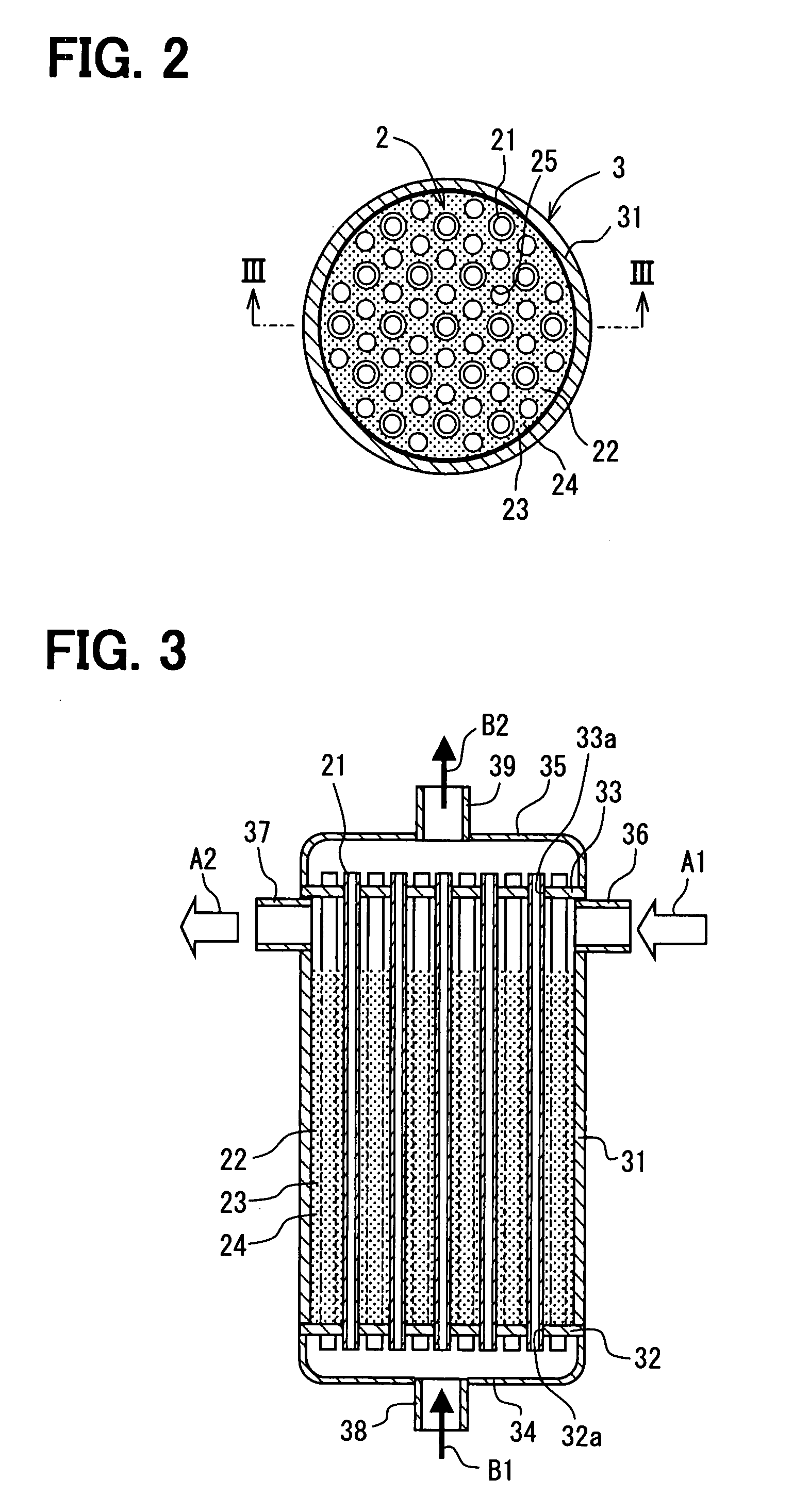
[0052]As shown in FIGS. 2 and 3, the adsorption module 1 generally includes a casing 3 and an adsorption heat exchanger (heat exchanging part) 2 housed in the casing 3. As shown in FIGS. 4A, 4B, and 6, the adsorption heat exchanger 2 includes heat medium pipes 21 through which a heat exchange medium (refrigerant) flows, a porous heat transferring member 23 disposed on peripheral areas (peripheral portions) 22 of the heat medium pipes 21, and adsorbent 24.
[0053]The heat medium pipes 21 are made of copper or coppe...
second embodiment
[0130]A second embodiment will be described with reference to FIGS. 15A and 15B. In the second embodiment, the adsorption module 1 has an adsorption heat exchanging part 102, which includes flat heat medium pipes 121, in a casing 103 as shown in FIG. 15A.
[0131]The porous heat transferring member 23 includes the adsorbent filled layers, that is, the peripheral portions 122. The peripheral portions 122 extend in the right and left direction of FIG. 15A and are arranged in the up and down direction in FIG. 15A at predetermined intervals. The flat heat medium pipes 121 are aligned in each peripheral portion 122 at predetermined intervals. In a cross-section defined in a direction perpendicular to the axis of the adsorption heat exchanger 102, longitudinal sides of the flat heat medium pipes 121 are parallel to a longitudinal side of the peripheral portion 122.
[0132]The adsorbed medium passage 125 is formed between the peripheral portions 122. The adsorbed medium passage 125 also has a f...
third embodiment
[0137]A third embodiment of the present invention will be described with reference to FIGS. 16A and 16B. In the third embodiment, the adsorption module 1 has an adsorption heat exchanging part 202 shown in FIG. 16A.
[0138]The heat exchanging part 202 includes the porous heat transferring member 23 that has adsorbent filled layers, that is, peripheral portions 222. The peripheral portions 222 are arranged at predetermined intervals in the right and left direction in FIG. 16A. The peripheral portions 222 extend in the up and down direction in FIG. 16A. The flat medium pipes 121 are arranged in a row in each peripheral portion 222. The flat medium pipes 121 are arranged such that the main surfaces of the adjacent heat medium pipes 121 are opposed to each other in the peripheral portion 222.
[0139]Further, adsorbed medium passages 225 are formed between the peripheral portions 222. In other words, the peripheral portions 222 and the adsorbed medium passages 225 are alternately arranged in...
PUM
| Property | Measurement | Unit |
|---|---|---|
| Distance | aaaaa | aaaaa |
| Distance | aaaaa | aaaaa |
| Distance | aaaaa | aaaaa |
Abstract
Description
Claims
Application Information