Symmetric blocking transient voltage suppressor (TVS) using bipolar transistor base snatch

a transistor base and transient voltage suppressor technology, applied in pulse manipulation, pulse technique, instruments, etc., can solve the problems of leakage current concerns, voltage variations, and technical difficulties of the technology of designing and manufacturing a bi-directional blocking transient voltage suppressor (tv)

Active Publication Date: 2008-04-03
ALPHA & OMEGA SEMICON LTD
View PDF6 Cites 29 Cited by
  • Summary
  • Abstract
  • Description
  • Claims
  • Application Information

AI Technical Summary

Benefits of technology

[0009]It is therefore an aspect of the present invention to provide a bi-directional symmetrical blocking TVS with a base that is connected to a lower potential such that the above-discussed difficulties and limitations encountered by the conventional bi-directional blocking TVS caused by a floating base can be overcome.

Problems solved by technology

The conventional technologies for designing and manufacturing a bi-directional blocking transient voltage suppressor (TVS) is still confronted with a technical difficulty that the base of a TVS device is connected to a terminal of floating potential.
However, such implementation often leads to a floating base that further leads to difficulties of voltage variations over time, i.e., the dV / dt.
The voltage variation over time further leads to the leakage current concerns due to the facts that when the base is floating, the voltage change dV / dt causes the equivalent capacitor generating charging and discharging currents that increase the leakage current.
However, in situations such as electrostatic discharge (ESD), electrical fast transients and lightning, an unexpected and an uncontrollable high voltage may accidentally strike onto the circuit.
However, the PN junction type of TVS has no minority carriers and has a poor clamping performance as that shown in FIG. 1B.
The floating base in these implementations causes the dV / dt issues and also the leakage concerns.

Method used


Image

  • Symmetric blocking transient voltage suppressor (TVS) using bipolar transistor base snatch
  • Symmetric blocking transient voltage suppressor (TVS) using bipolar transistor base snatch
  • Symmetric blocking transient voltage suppressor (TVS) using bipolar transistor base snatch

Examples


Embodiment Construction

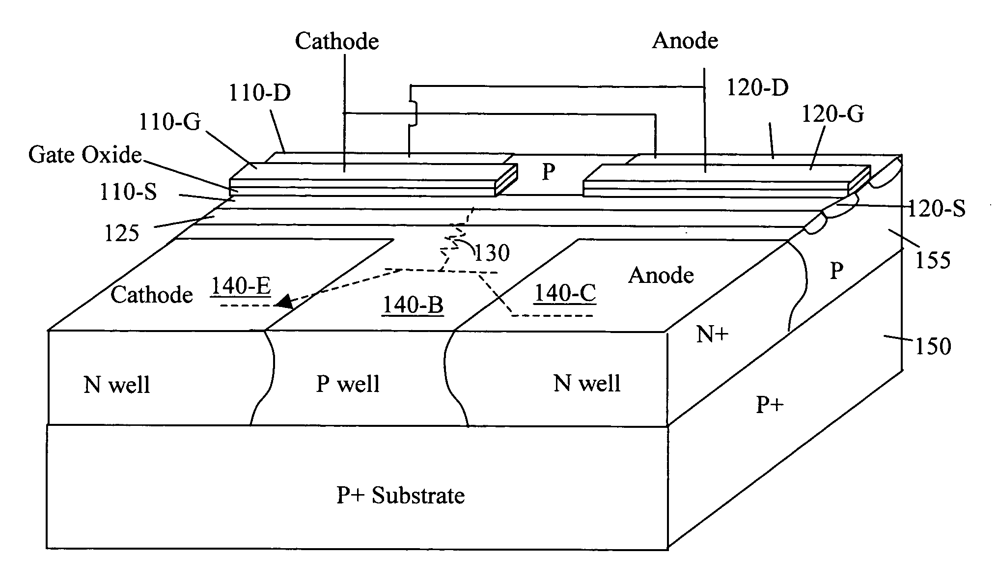
[0023]Referring to FIG. 3A for a circuit diagram of new and improved TVS that has a bi-directional symmetric blocking function. The TVS 100 includes two MOSFET transistors. The first transistor 110 shown as M1 has a source terminal 110-S connected to a source terminal 120-S of a second transistor 120 shown as M2. The first transistor 110 further has a drain terminal 110-D connected to a high voltage terminal 105 with a voltage Vcc and a gate terminal 110-G connected to a ground terminal 99 with a voltage GND. The second transistor 120 further has a drain terminal connected to the ground terminal GND and a gate terminal connected to the high voltage terminal Vcc. The interconnected point 125 of the source terminals of the first transistor 110 and second transistor 120 is further connected via a resistor 130 to a base of a NPN transistor 140 connected in parallel between the main voltage terminal Vcc and the ground terminal GND, with emitter connected to GND and collector connected to...


PUM

PropertyMeasurementUnit
transient voltageaaaaaaaaaa
voltage potentialaaaaaaaaaa
breakdown voltageaaaaaaaaaa

Abstract

A symmetrical blocking transient voltage suppressing (TVS) circuit for suppressing a transient voltage includes an NPN transistor having a base electrically connected to a common source of two transistors whereby the base is tied to a terminal of a low potential in either a positive or a negative voltage transient. The two transistors are two substantially identical transistors for carrying out a substantially symmetrical bi-directional clamping a transient voltage. These two transistors further include a first and second MOSFET transistors having an electrically interconnected source. The first MOSFET transistor further includes a drain connected to a high potential terminal and a gate connected to the terminal of a low potential and the second MOSFET transistor further includes a drain connected to the terminal of a low potential terminal and a gate connected to the high potential terminal.

Description

BACKGROUND OF THE INVENTION[0001]1. Field of the Invention[0002]The invention relates generally to a circuit configuration and method of manufacturing a transient voltage suppressor (TVS). More particularly, this invention relates to an improved circuit configuration and method of manufacturing a symmetrical bi-directional blocking transient voltage suppressor (TVS) implemented with bipolar transistor base snatch to connect the base to a low potential terminal.[0003]2. Description of the Relevant Art[0004]The conventional technologies for designing and manufacturing a bi-directional blocking transient voltage suppressor (TVS) is still confronted with a technical difficulty that the base of a TVS device is connected to a terminal of floating potential. Typically, the bi-directional blocking TVS is implemented with symmetric NPN / PNP configuration with identical emitter-base and collector-base breakdown voltage. However, such implementation often leads to a floating base that further l...

Claims


Application Information

Patent Timeline
Patent Type & Authority Applications(United States)
IPC IPC(8): H01L29/80
CPCY10T29/49002H01L27/0259H01L21/74H01L29/73H01L29/80
Inventor BOBDE, MADHUR
Owner ALPHA & OMEGA SEMICON LTD
Why Eureka
Try Eureka