Magneto-resistance effect element, magnetic head, magnetic recording/reproducing device and magnetic memory

a technology of resistance effect and magnetic head, which is applied in the direction of magnetic body, record information storage, instruments, etc., can solve the problem of excessive resistan

Inactive Publication Date: 2008-04-03
KK TOSHIBA +1
View PDF52 Cites 17 Cited by
  • Summary
  • Abstract
  • Description
  • Claims
  • Application Information

AI Technical Summary

Benefits of technology

[0033]FIG. 1 is a perspective view illustrating a magneto-resistance effect element according to an embodiment of the present invention. Some or all components throughout the drawings in the present application are schematically illustrated so that the illustrated sizes (thickness) and thickness ratio for the components is different from the real sizes and thickness ratio for the components.
[0034]The magneto-resistance effect element 10 illustrated in FIG. 1 includes a bottom electrode LE and a top electrode UE which are disposed so as to sandwich a plurality of layers composing the magneto-resistance effect element 10. Concretely, the magneto-resistance effect element 10 is configured such that an underlayer 11, an antiferromagnetic layer 12, a complex pinned layer 13, an intermediate layer 14, a free layer 15 and a protective layer 16 are subsequently formed on the bottom electrode LE. The complex pinned layer 13 is configured such that a magnetic anti-parallel coupling layer 132 is sandwiched between a first pinned layer 131 and a second pinned layer 132. The intermediate layer 14 is composed of insulating portions 141 and magnetic metallic portions 142 which are disposed alternately in the intermediate layer 14.
[0035]In this embodiment, the complex pinned layer 13, the intermediate layer 14 and the free layer 15 constitute the spin valve film.
[0036]The complex pinned layer 13 correspond

Problems solved by technology

However, too small size of the minute magnetic coupling point may increase the resistance thereof excessively.
The increase of the interlayer-couplin

Method used


Image

  • Magneto-resistance effect element, magnetic head, magnetic recording/reproducing device and magnetic memory
  • Magneto-resistance effect element, magnetic head, magnetic recording/reproducing device and magnetic memory
  • Magneto-resistance effect element, magnetic head, magnetic recording/reproducing device and magnetic memory

Examples


example 1

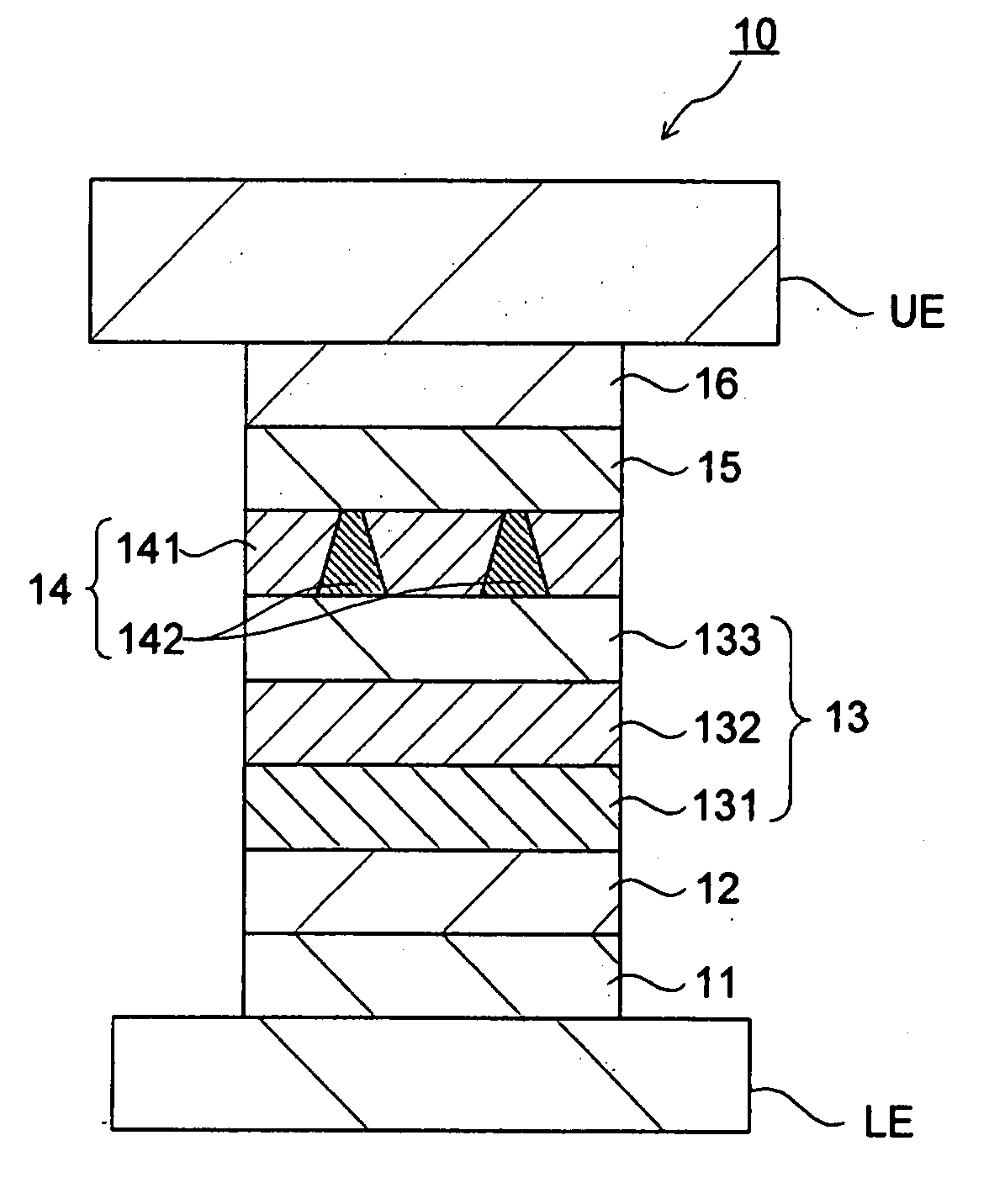
[0084]Example 1 relating to the magneto-resistance effect element 10 will be described. In Example 1, the magneto-resistance effect element 10 was formed as follows:[0085]Underlayer 11: Ta 5 nm / NiFeCr 7 nm[0086]Antiferromagnetic layer 12: PtMn 15 nm[0087]First pinned layer 131: Co9Fe1 3.3 nm[0088]Magnetic antiparallel coupling layer 132: Ru 0.9 nm[0089]Second pinned layer 132: Fe5Co5 2.5 nm / Cu 0.1 nm

[0090]The underlayer 11 through the second pinned layer 132 were subsequently formed. Then, the Al layer with a thickness of 0.9 nm was formed and oxidized under Ar ion atmosphere. Then, the ion treatment was carried out to form the multilayered structure of the intermediate layer 14: the Al oxide / FeCo—Cu metallic layer. Then,[0091]Free layer 15: Fe5Co5 2.5 nm[0092]Protective layer 16: Cu 1 nm / Ta 2 nm / Ru 15 nm

were formed.

[0093]The thus obtained magneto-resistance effect element 10 was thermally treated at 270° C. during ten hours under magnetic field. As a result, in Example 1, the RA of...

example 2

[0094]Example 2 relating to the magneto-resistance effect element 10 will be described. In Example 2, the magneto-resistance effect element 10 was formed as follows:[0095]Underlayer 11: Ta 5 nm / Ru 2 nm[0096]Antiferromagnetic layer 12: PtMn 15 nm[0097]First pinned layer 131: Co9Fe1 3.3 nm[0098]Magnetic antiparallel coupling layer 132: Ru 0.9 nm[0099]Second pinned layer 132: Fe5Co5 2.5 nm / Cu 0.1 nm

[0100]The underlayer 11 through the second pinned layer 132 were subsequently formed. Then, the Al layer with a thickness of 0.9 nm was formed and oxidized under Ar ion atmosphere. Then, the ion treatment was carried out to form the multilayered structure of the intermediate layer 14: the Al oxide / FeCo—Cu metallic layer. Then,[0101]Free layer 15: Fe5Co5 2.5 nm[0102]Protective layer 16: Cu 1 nm / Ta 2 nm / Ru 15 nm

were formed.

[0103]The thus obtained magneto-resistance effect element 10 was thermally treated at 270° C. during ten hours under magnetic field. As a result, in Example 2, the RA of the...

example 3

[0104]Example 3 relating to the magneto-resistance effect element 10 will be described. In Example 3, the magneto-resistance effect element 10 was formed as follows:[0105]Underlayer 11: Ta 5 nm / NiFeCr 7 nm[0106]Antiferromagnetic layer 12: PtMn 15 nm[0107]First pinned layer 131: Co9Fe1 3.3 nm[0108]Magnetic antiparallel coupling layer 132: Ru 0.9 nm[0109]Second pinned layer 132: Fe5Co5 2.5 nm / Zr 0.1 nm

[0110]The underlayer 11 through the second pinned layer 132 were subsequently formed. Then, the Al layer with a thickness of 0.9 nm was formed and oxidized under Ar ion atmosphere. Then, the ion treatment was carried out to form the multilayered structure of the intermediate layer 14: the Al oxide / FeCo—Zr metallic layer. Then,[0111]Free layer 15: Fe5Co5 2.5 nm[0112]Protective layer 16: Cu 1 nm / Ta 2 nm / Ru 15 nm

were formed.

[0113]The thus obtained magneto-resistance effect element 10 was thermally treated at 270° C. during ten hours under magnetic field. As a result, in Example 3, the RA of...


PUM


Abstract

A magneto-resistance effect element includes: a first magnetization layer of which a magnetization is substantially fixed in one direction; a second magnetization layer of which a magnetization is rotated in accordance with an external magnetic field; an intermediate layer which contains insulating portions and magnetic metallic portions and which is provided between the the first magnetic layer and the second magnetic layer; and a pair of electrodes to flow current in a direction perpendicular to a film surface of a multilayered film made of the first magnetic layer, the intermediate layer and the second magnetic layer; wherein the magnetic metallic portions of the intermediate layer contain non-ferromagnetic metal.

Description

CROSS-REFERENCE TO RELATED APPLICATIONS[0001]This application is based upon and claims the benefit of priority from the prior Japanese Patent Application No. 2006-265836, filed on Sep. 28, 2006; the entire contents of which are incorporated herein by reference.BACKGROUND OF THE INVENTION[0002]1. Field of the Invention[0003]The present invention relates to a magneto-resistance effect element which is configured such that a current is flowed in the direction perpendicular to the film surface thereof. The present invention also relates to a magnetic head, a magnetic recording / reproducing device and a magnetic memory which utilize the magneto-resistance effect element according to the present invention.[0004]2. Description of the Related Art[0005]Recently, the performance of a magnetic device, particularly such as a magnetic head is enhanced by means of Giant Magneto-Resistance Effect (GMR) made of a multilayered magnetic structure. Particularly, since a spin valve film (SV film) can ex...

Claims


Application Information

Patent Timeline
IPC IPC(8): G11B5/33
CPCB82Y25/00B82Y40/00G01R33/093G11B5/3906G11B5/398H01F10/3259G11C11/16H01F10/3272H01F41/305H01L43/08G11B5/3983G11C11/161H10N50/10
Inventor FUKE, HIROMIHASHIMOTO, SUSUMUTAKAGISHI, MASAYUKIIWASAKI, HITOSHI
Owner KK TOSHIBA
Why Eureka
Try Eureka