Robotic apparatus with non-conductive wrist for painting

a technology of non-conductive wrist and robotic equipment, which is applied in the direction of superimposed coating process, liquid/solution decomposition chemical coating, manufacturing tools, etc., can solve the problems of inefficient use of allotted painting cycle time, lack of flexibility to provide optimized standoff, and good portion of available cycle time unused

Active Publication Date: 2008-04-10
FANUC ROBOTICS NORTH AMERICA
View PDF25 Cites 33 Cited by
  • Summary
  • Abstract
  • Description
  • Claims
  • Application Information

AI Technical Summary

Benefits of technology

[0034]FIG. 10 is an enlarged exploded perspective view of the canister quick disconnect shown in FIG. 9; an

Problems solved by technology

Another painting device is used in the same painting zone to paint the sides of the body and generally does not have the capability to move laterally along the length of the body.
Disadvantages of this type of painting apparatus include lack of flexibility to provide optimized standoff distance between the body surface and the applicator along with inefficient use of the allotted painting cycle time.
They can only paint the portion of the body that is in front of the applicator leaving a good portion of the available cycle time unused.
The prior art floor mounted robots, especially bell machines, are inherently very costly and limit visual access to the spray booth.
The bell machines require more bells for the same throughput due to limited orientation capability.
Prior art floor mounted robots also require significant booth modification when installed in existing paint booths, increasing installation time and cost, and require more booth length and width.
Floor mounted robots also require frequent cleaning due to the down draft of paint overspray causing paint accumulation on the robot arm and base, which results in higher maintenance and cleaning costs.
The prior art bell zone machines also lack flexibility.
Additional an

Method used


Image

  • Robotic apparatus with non-conductive wrist for painting
  • Robotic apparatus with non-conductive wrist for painting
  • Robotic apparatus with non-conductive wrist for painting

Examples


Embodiment Construction

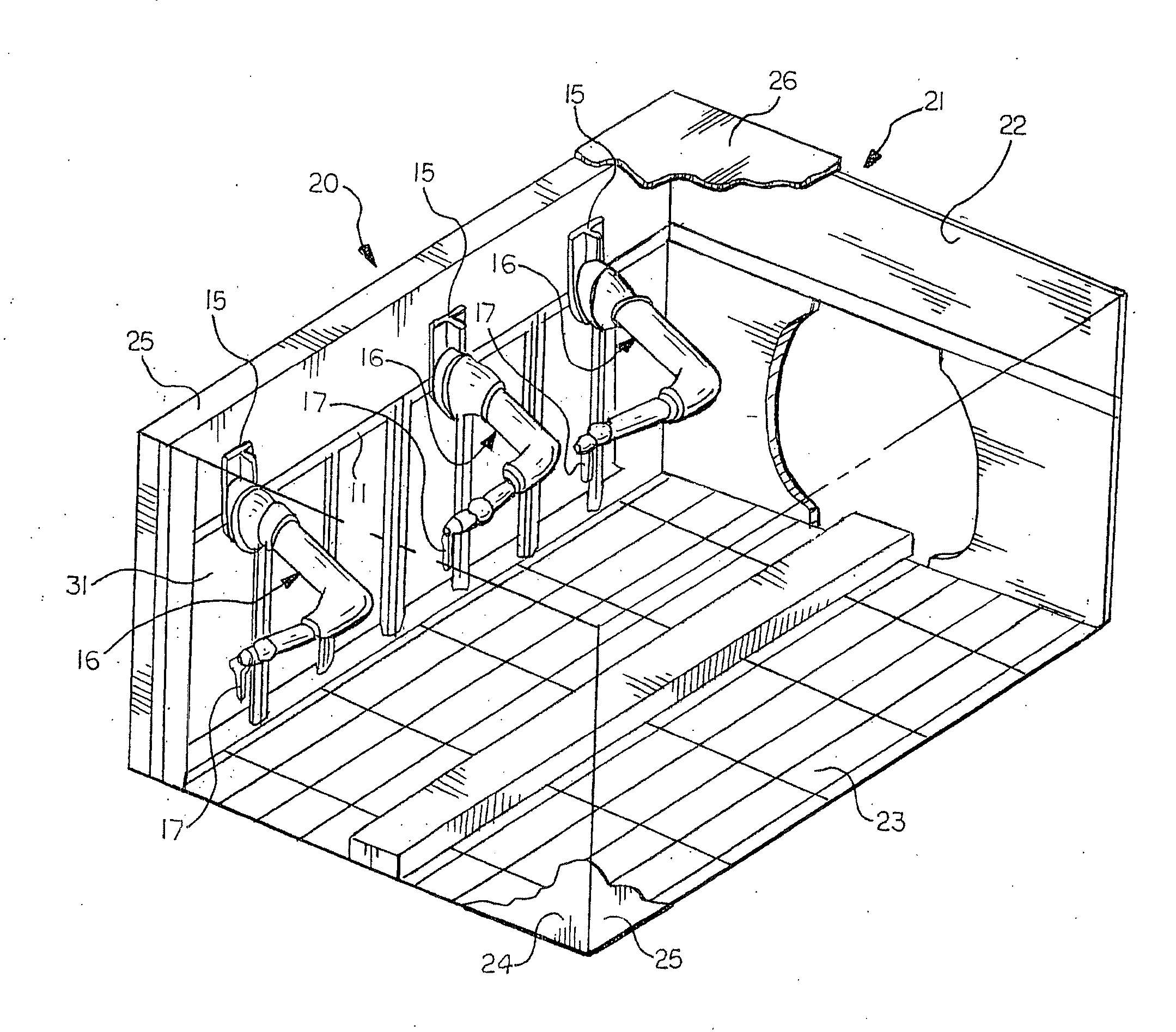
[0036] There is shown in FIG. 1a modular elevated rail apparatus 10 for painting articles or objects in accordance with the present invention. The elevated rail apparatus 10 is adapted to be disposed in a paint booth as discussed below. The apparatus 10 includes a pair of frame rails 11 extending in a horizontal direction and spaced apart a predetermined distance on opposite sides of an axis 12 defining a path of travel for objects to be painted. Each end of each of the frame rails 11 is supported on an upper end of an associated one of a plurality of legs 13 adapted to engage a floor of the painting booth. Corresponding ends of the frame rails 11 can be connected by cross support members 14 that cooperate with the frame rails 11 and the legs 13 to form a modular, rigid supporting frame structure of the apparatus 10. If required for support, additional ones of the legs 13 and the members 14 can be attached intermediate the ends of the frame rails 11.

[0037] The frame rails 11 each h...


PUM

PropertyMeasurementUnit
Coloraaaaaaaaaa
Electrical conductoraaaaaaaaaa
Electric potential / voltageaaaaaaaaaa

Abstract

A painting robot outer arm includes a non-conductive housing mounting a color changer on the outside and a paint canister on the inside connected by an isolating paint transfer line. The paint canister is releasably attached to a piston ram and drive motor by a quick disconnect coupling. The paint supply is isolated from the applied high voltage by cleaning and drying the transfer line. The rate of filling of the canister can be controlled in response to sensed torque applied by a drive motor moving a piston in the paint canister.

Description

CROSS-REFERENCE TO RELATED APPLICATION [0001] This application claims the benefit of U.S. provisional patent application Ser. No. 60 / 420,612 filed Oct. 23, 2002, the U.S. provisional patent application Ser. No. 60 / 420,971 filed Oct. 24, 2002, and the U.S. provisional patent application Ser. No. 60 / 423,636 filed Nov. 4, 2002. [0002] This application is a continuation of the co-pending U.S. patent application Ser. No. 10 / 691,939 filed Oct. 23, 2003.BACKGROUND OF THE INVENTION [0003] The present invention relates generally to robotic painting systems and in particular to a robotic apparatus for applying electrically conductive paint to the external surfaces of automotive vehicle bodies. [0004] Prior art paint booths are well known. A typical prior art paint booth, used to paint the exterior surfaces of vehicle bodies in both continuous conveyance and stop station systems, includes an enclosure housing a plurality of paint applicators. In one configuration, the applicators are mounted o...

Claims


Application Information

Patent Timeline
IPC IPC(8): B05B3/00B05C11/00B05D1/02B05B12/14B05B13/04
CPCB05B12/14B05B13/0452B05B13/0431B25J11/0075B25J19/0075
Inventor CLIFFORD, SCOTT J.COPIOLI, PAUL D.BEEM, MICHAEL G.FOTI, ROBERT C.MCCLOSKY, STAN H.ZIMMERER, MATTNIEDERQUELL, BRAD O.MANTZ, W. DANIEL
Owner FANUC ROBOTICS NORTH AMERICA
Why Eureka
Try Eureka