Nanoporous stents with enhanced cellular adhesion and reduced neointimal formation

a stent and nanoporous technology, applied in the field of nanoporous stents with enhanced cellular adhesion and reduced neointimal formation, can solve the problems of porous alumina with severe mechanical integrity problems, limited coating adhesion, mechanical properties, etc., and achieve the effect of enhancing the efficacy of the implantable devi

Active Publication Date: 2008-04-10
UNIV OF VIRGINIA ALUMNI PATENTS FOUND
View PDF69 Cites 69 Cited by
  • Summary
  • Abstract
  • Description
  • Claims
  • Application Information

AI Technical Summary

Benefits of technology

[0005] Implantable medical devices are increasingly being used to deliver one or more therapeutic agents to a site within a body. Such agents may provide their own benefits to treatment and/or may enhance the efficacy of the implantable device. For example, much research has been conducted into the use of drug eluting stents for use in percutaneous

Problems solved by technology

Polymer coatings, for example, have limitations related to coating adhesion, mechanical properties, inflammatory pr

Method used


Image

  • Nanoporous stents with enhanced cellular adhesion and reduced neointimal formation
  • Nanoporous stents with enhanced cellular adhesion and reduced neointimal formation
  • Nanoporous stents with enhanced cellular adhesion and reduced neointimal formation

Examples


example a

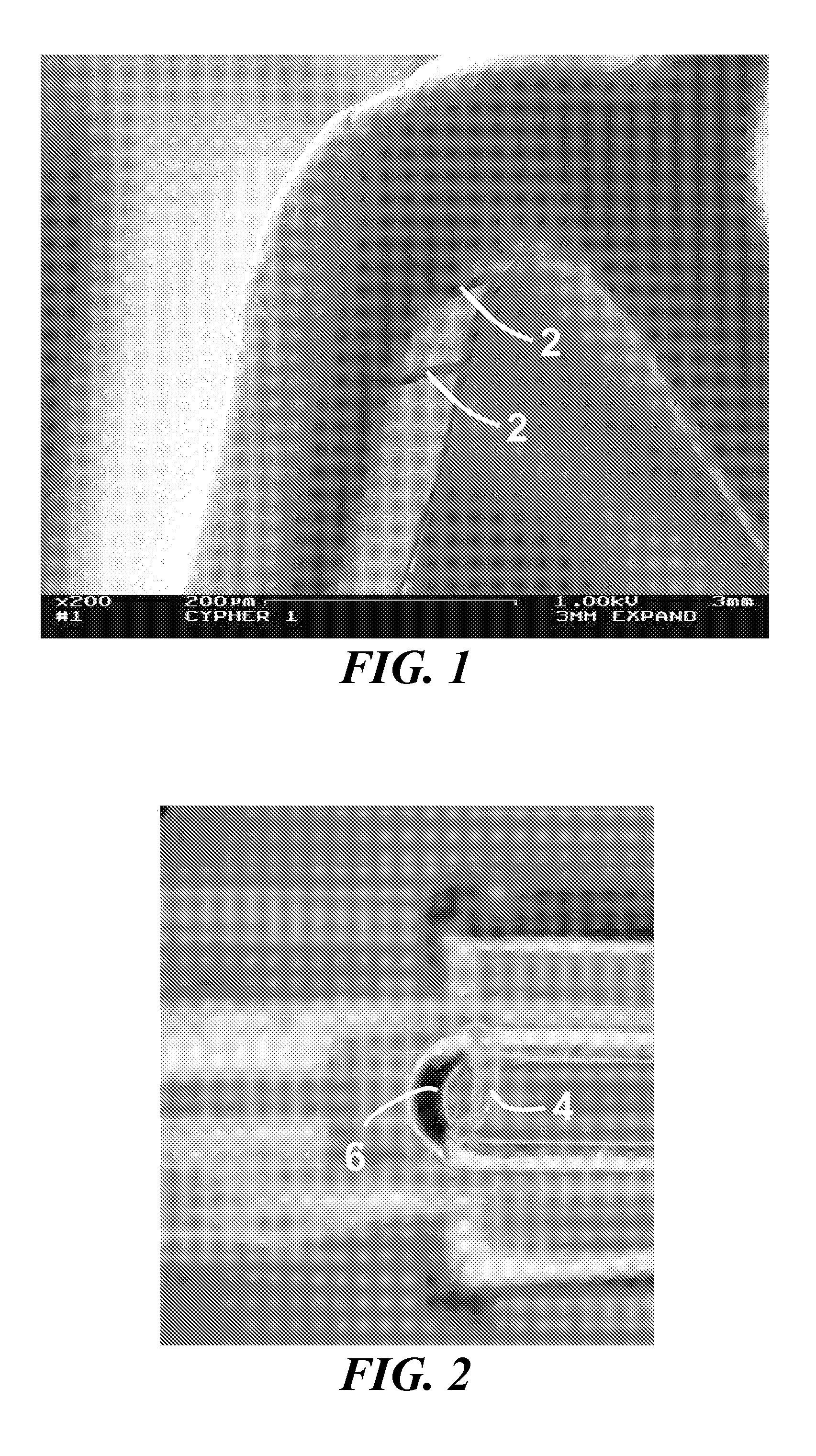
[0214] In one specific example, a coronary stent is co-sputtered with L605 (3.1 A / s) and magnesium (9.7 A / s) in 2×10⁻³ torr Argon, resulting in an alloy coating that is approximately 30% by weight of magnesium. The stent is dealloyed using a 1% HNO3 at about 1° Celsius for about 5 minutes, followed by an anneal at about 600° Celsius for 10 minutes at about 10−5 torr vacuum with a ramp rate of about 200° Celsius / minute. This process produces a dealloyed layer as depicted in the scanning electron micrograph in FIG. 18. The resulting porous zone is approximately 3% by weight of magnesium and has a range of pore sizes from about 1 nm to about 25 nm.

[0215] In a further embodiment, the stent may be loaded with rapamycin using a procedure whereby the stent is washed using absolute ethanol in a gently agitation of about 40 rpm for about 1 hour. The stent is then placed in a vacuum chamber along with a 7″×5″ reservoir of about 100 mL of absolute ethanol. The vacuum pump is set to a setting ...

example b

[0216] In another specific example, a coronary stent is co-sputtered with L605 (1.5 A / s) and magnesium (12 A / s) in 2×10⁻³ torr Argon for a resulting alloy coating that is approximately 80% by weight of magnesium. The stent is dealloyed using a 1% HNO3 at about 1° Celsius for about 5 minutes, followed by an anneal at about 600° Celsius for 10 minutes at about 10−5 torr vacuum with a ramp rate of about 200° Celsius / minute. This process produces a dealloyed layer as depicted in the scanning electron micrograph in FIG. 19. The resulting porous zone is approximately 5% by weight of magnesium and has a range of pore sizes from about 10 nm to about 200 nm. In a further embodiment, this stent is loaded with rapamycin using the same procedure as disclosed in Example A, resulting in an initial payload of about 85 micrograms. Place in an in vivo porcine coronary artery stent model results in a 7 day tissue concentration of about 0.80 ng / mg of tissue as measured by tandem MS / MS HPLC.

example c

[0217] In still another specific example, a coronary stent undergoes a lower layer sputter deposition with L605 (1.5 A / s) and magnesium (12 A / s) in 2×10⁻³ torr Argon, and followed by an additional upper layer co-sputtering with L605 (3.1 A / s) and Mg (9.7 A / s) in 2×10⁻³ torr Argon, for a resulting alloy coating has a lower layer thickness of about 750 nm and an upper layer with a thickness of about 75 nm. Optionally, one or both sputtering steps may be repeated one or more times, in an alternating or other desired order, to create a layered columnar porous zone. In one embodiment, shown in FIG. 20, an additional two high magnesium content layers, with one lower magnesium content layer is sputtered to produce a five layer porous stent surface. The stent is dealloyed using a 1% HNO3 at about 1° Celsius for about 5 minutes, followed by an anneal at about 600° Celsius for 10 minutes at about 10−5 torr vacuum with a ramp rate of about 200° Celsius / minute. The resulting porous zone has a r...


PUM


Abstract

The present invention relates generally to medical devices containing nanoporous surfaces and methods for making same. More specifically, the invention relates to implantable vascular stents or other biomedical devices having at least one nanoporous layer that promotes improved cellular adhesion properties that promote healing and long term biocompatibility. In the case of stents, the nanoporous layer promotes re-endothelialization at sites of stent implantation vasculature, improves overall healing, and reduces inflammation and intimal disease progression. The nanoporous layer may be optionally loaded with one or more therapeutic agent to further improve the function of the implanted stent and further augment clinical efficacy.

Description

CROSS-REFERENCE TO RELATED APPLICATIONS [0001] The present application claims priority under 35 U.S.C. §119(e) to U.S. Provisional Application No. 60 / 809,465 filed on May 31, 2006, and is also a continuation-in-part of U.S. application Ser. No. 11 / 200,655 filed Aug. 10, 2005, which 1) claims priority under 35 U.S.C. §119(e) to U.S. Provisional Application No. 60 / 602,542 filed on Aug. 18, 2004, U.S. Provisional Application No. 60 / 613,165 filed on Sep. 24, 2004, U.S. Provisional Application No. 60 / 664,376 filed on Mar. 23, 2005, and U.S. Provisional Application Ser. No. 60 / 699,302 filed Jul. 14, 2005, and 2) is a continuation-in-part of U.S. application Ser. No. 10 / 918,853 filed on Aug. 13, 2004, which is a continuation-in-part of U.S. application Ser. No. 10 / 713,244 filed on Nov. 13, 2003, which claims priority under 35 U.S.C. §119(e) to U.S. Provisional Application No. 60 / 426,106 filed on Nov. 13, 2002, the disclosures of which are incorporated by reference herein in their entirety....

Claims


Application Information

Patent Timeline
IPC IPC(8): A61F2/06
CPCA61F2/91A61F2/82A61F2240/001A61F2250/0058
Inventor OWENS, GARYLYE, WHYE-KEIREED, MICHAELSPRADLIN, JOSHUAWAMHOFF, BRIANHUDSON, MATTHEWLOOI, KAREEN
Owner UNIV OF VIRGINIA ALUMNI PATENTS FOUND
Why Eureka
Try Eureka