IGCC design and operation for maximum plant output and minimum heat rate

a technology of igcc and maximum plant output, applied in steam engine plants, machines/engines, mechanical equipment, etc., can solve the problems of igcc systems still suffering from some disadvantages when compared to other systems, igcc plants, conventional igcc power plants to reduce output, etc., and achieves the effect of reducing efficiency and increasing outpu

Inactive Publication Date: 2008-04-17
SIEMENS ENERGY INC
View PDF22 Cites 25 Cited by
  • Summary
  • Abstract
  • Description
  • Claims
  • Application Information

AI Technical Summary

Benefits of technology

[0011]The invention is directed to an integrated gasification combined cycle (IGCC) gas turbine system having a design operation point for the chemical potential energy and the sensible energy of the fuel stream entering the combustion turbine. The IGCC system of the present invention achieves the target output, efficiency, or both by adjusting the fuel stream chemical potential energy, sensible energy, or both. The IGCC system utilizes the fuel stream to control the operation of the IGCC gas turbine system to achieve a target output or efficiency. The IGCC system may operate at a part load without a corresponding drop in efficiency as found in conventional gas turbine systems. Additionally, an IGCC system of the invention may operate at higher outputs. These fuel stream energy characteristics may be manually or automatically controlled to achieve the target output, efficiency, or both.

Problems solved by technology

Nevertheless, IGCC systems still suffer from some disadvantages when compared to other systems.
Another disadvantage is that IGCC plants are normally designed to operate at a design operation point for output and efficiency.
This lack of flexibility causes conventional IGCC power plants to reduce output, i.e. part load the gas turbine, by partially closing the Inlet Guide Vanes (IGVs), reducing the firing temperature of the combustor, or a combination of both.
Both of these control mechanisms result in a reduction of IGCC efficiency at power output levels less than the design operation point.

Method used


Image

  • IGCC design and operation for maximum plant output and minimum heat rate
  • IGCC design and operation for maximum plant output and minimum heat rate
  • IGCC design and operation for maximum plant output and minimum heat rate

Examples


Embodiment Construction

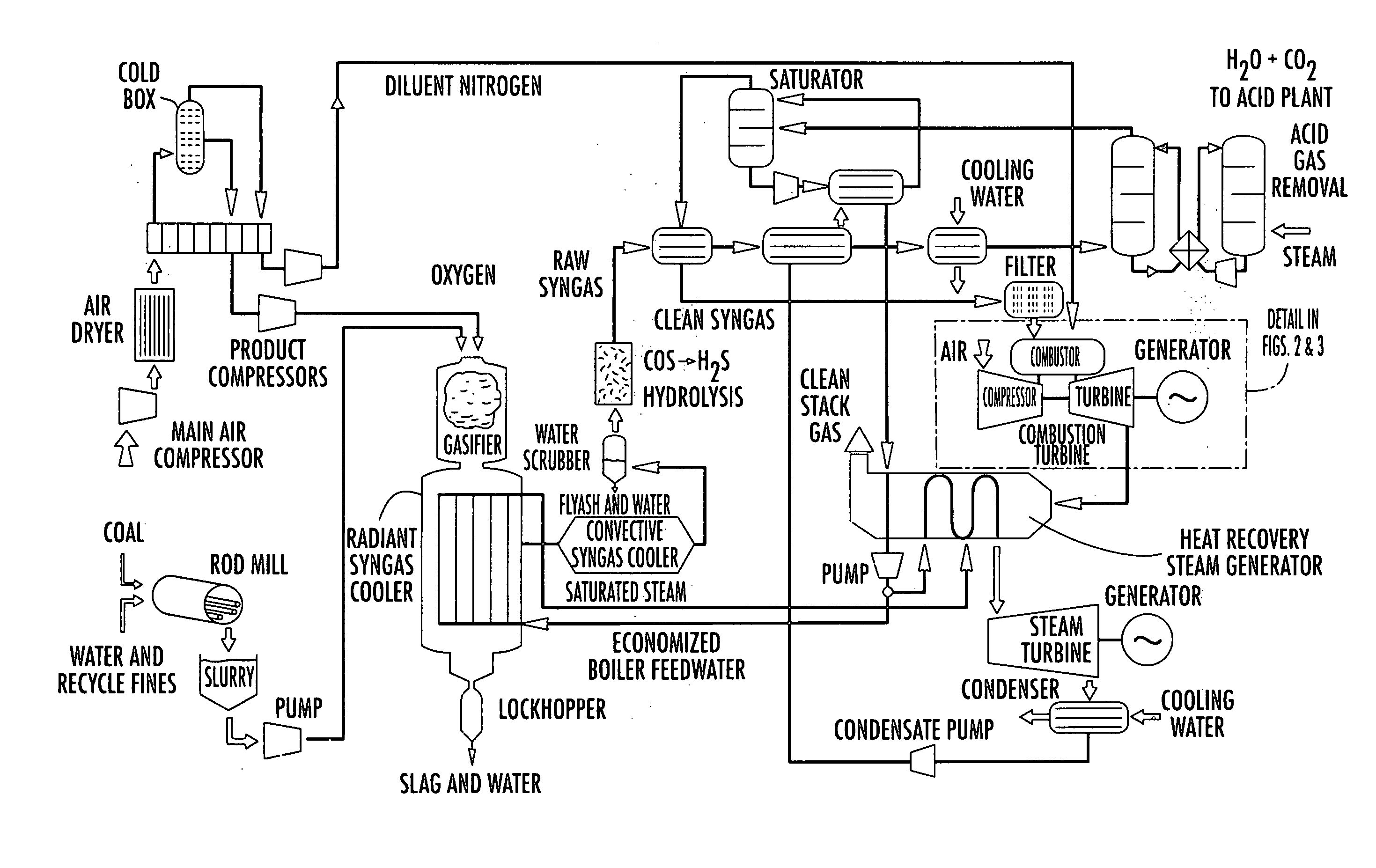
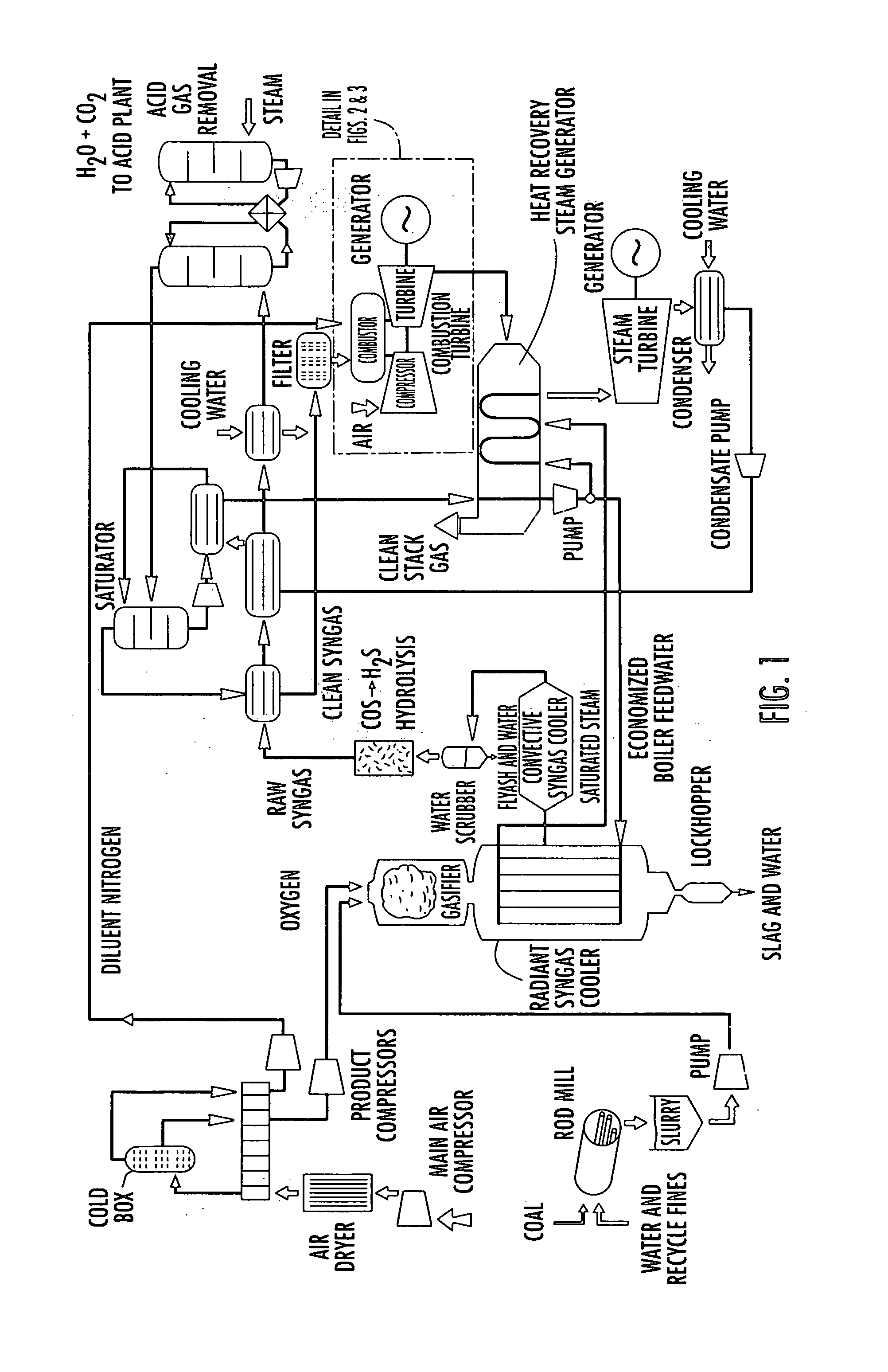
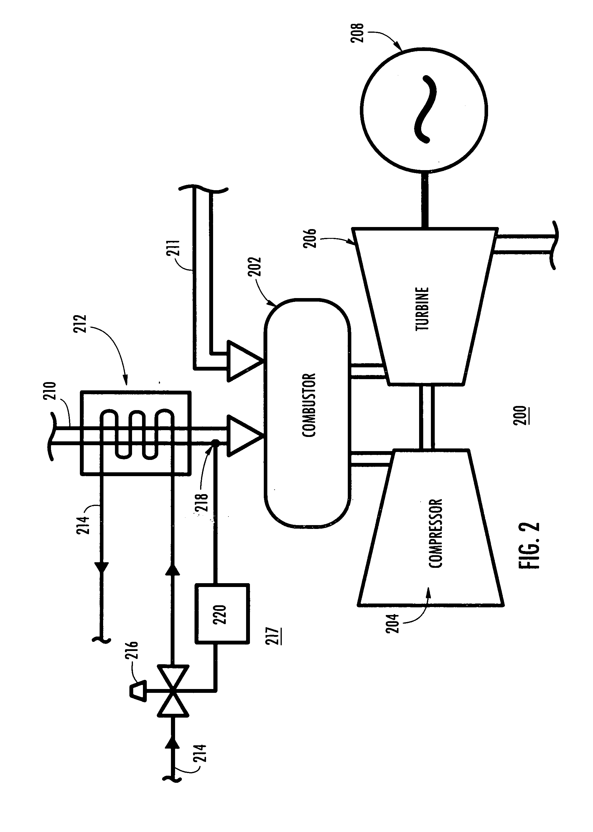
[0022]As shown in FIGS. 1-6, the present invention is directed to a, IGCC gas turbine system 10 and a method of determining a target output and a target efficiency of the IGCC system 10 and adjusting one or more fuel energy characteristic to achieve the target output and a target efficiency. As used herein, “fuel energy characteristic” refers to both the chemical potential energy and the sensible energy of the fuel.

[0023]An IGCC system, as depicted in FIG. 1, may be designed to operate at a design operation point for the temperature and heating value of the fuel entering the combustor. Accordingly, plant systems, components, and controls are structured to meet the design operation point temperature and heating value. Because syngas has a heating value that is roughly 1 / 10th that of natural gas diluted to meet gas turbine (GT) requirements, more fuel is generally needed to operate a gas turbine at the design operation point turbine temperature in an IGCC plant. For a gas turbine in a...


PUM


Abstract

A system and method for operating an integrated gasification combined cycle (IGCC) gas turbine system that utilizes the fuel stream as a means of controlling the operation of the IGCC to achieve a target output and efficiency. The methods and systems enable the IGCC to be operated at reduced output, but without a corresponding drop in efficiency as compared to prior art gas turbine systems. Conversely, the IGCC may be operated at higher outputs. The methods and systems achieve the target output and efficiency by adjusting the chemical potential energy, sensible energy, or both of a fuel stream entering the combustion turbine. The chemical potential energy and sensible energy may be manually or automatically controlled.

Description

FIELD OF THE INVENTION[0001]The present invention is directed generally to gas turbine systems, and more particularly to integrated gasification combined cycle gas turbine systems.BACKGROUND OF THE INVENTION[0002]The utilization of coal in the prior art has been minimized due to undesirable emissions, such as oxides of nitrogen and sulfur, particulate emissions and greenhouse gases such as carbon dioxide. As a result, there have been efforts to reduce these emissions and improve fuel efficiency of coal plants.[0003]One of the systems that have been developed is the Integrated Gasification Combined Cycle (IGCC) system for use in power generation. IGCC systems were devised as a way to use coal as the fuel source for a gas turbine plant. IGCC systems are clean and generally more efficient than conventional coal plants.[0004]IGCC is a combination of two systems. The first system is coal gasification, which uses coal to create a clean-burning synthetic gas (“syngas”). The gasification po...

Claims


Application Information

Patent Timeline
Patent Type & Authority Applications(United States)
IPC IPC(8): F02C1/00
CPCF01K23/068F02C3/28Y02E20/16Y02E20/18F02C9/40
Inventor BRIESCH, MICHAEL SCOTSULLIVAN, TERRENCE BLAISE
Owner SIEMENS ENERGY INC
Why Eureka
Try Eureka