
Anti-scatter grid and collimator designs, and their motion, fabrication and assembly

a collimator and anti-scatter technology, applied in the field of focused and unfocused grids and collimators, can solve the problems of grid pattern and associated motion, requiring an increase in x-ray dose, and difficult interpretation, so as to reduce scattering of radiation, eliminate undesirable radiation detection, and improve image resolution

Active Publication Date: 2008-04-17
CREATV MICROTECH
View PDF0 Cites 29 Cited by
  • Summary
  • Abstract
  • Description
  • Claims
  • Application Information

AI Technical Summary

Benefits of technology

[0032] Another objective of the present invention is to configure the grids to minimize shadow when the grid is moved during imaging.
[0033] A further object of the present invention is to provide a method and apparatus for moving a focused or unfocused grid so that no perceptible shadow or area of variable density is cast by the grid onto the imager.
[0035] Another object of the present invention is to provide a method and apparatus for manufacturing focused and unfocused grids that are configured to minimize overexposure at wall intersections when a grid is moved during imaging.
[0038] These and other objects are further substantially achieved by providing a method for minimizing scattering of radiation in a device to obtain an image of an object on an imager. The method includes placing a grid between radiation emitting source of the electromagnetic imaging device and the imager. The grid comprises at least one metal layer including top and bottom surfaces and a plurality of solid integrated, intersecting walls, each of which extending from the top to bottom surface and having a plurality of side surfaces, the side surfaces of the walls being arranged to define a plurality of openings extending entirely through the layer, and at least some of the side surface having projections extending into respective ones of the openings. The method further includes moving the grid in a grid moving pattern while the radiation source is emitting radiation toward the imager.
[0039] In addition, the holes of one or more layers of a grid or collimator produced by the present invention can be filled with various materials that are transparent, opaque, or have other properties, such as scintillators. Examples of scintillator are phosphors, CsI, or the like. Since grids and collimators can be reproduced exactly, an air-core grid or collimator can be aligned precisely with the filled-core grid or collimator counterpart. The desired thickness of the filling can also be achieved precisely. This type of grid / scintillator or collimator / scintillator, therefore, can performs the functions of (1) eliminating detection of undesirable radiation, (2) conversion of x-rays or γ-rays to optical or UV signals or other forms of signals and (3) improving resolution of the image or (4) improve the structural strength or other properties of the device.

Problems solved by technology

The disadvantages associated with this type of one-dimensional grid are that it only reduces scattered x-rays parallel to the strips and that it requires an increase in x-ray dose because of absorption and scatter from the spacer materials.
It is undesirable, since it can obstruct the image and make interpretation more difficult.
This grid pattern and associated motion are unacceptable.
However, these methods are unacceptable or not ideal for many applications.
Foil collimators can be mad from foil as thin as 100 μm, but they are more susceptible to defects in foil misalignment, resulting in reduced resolution and uniformity of the image.
However, micro-casting manufactures, such as Nuclear Fields, cannot make septa thinner than 150 μm.
This technology, however, is (a) limited in the septa thickness, (b) unable to fabricate focused cone beam collimators with smooth walls, and unable to fabricate collimators requiring large slant septa.

Method used


Image

  • Anti-scatter grid and collimator designs, and their motion, fabrication and assembly
  • Anti-scatter grid and collimator designs, and their motion, fabrication and assembly
  • Anti-scatter grid and collimator designs, and their motion, fabrication and assembly

Examples


Embodiment Construction

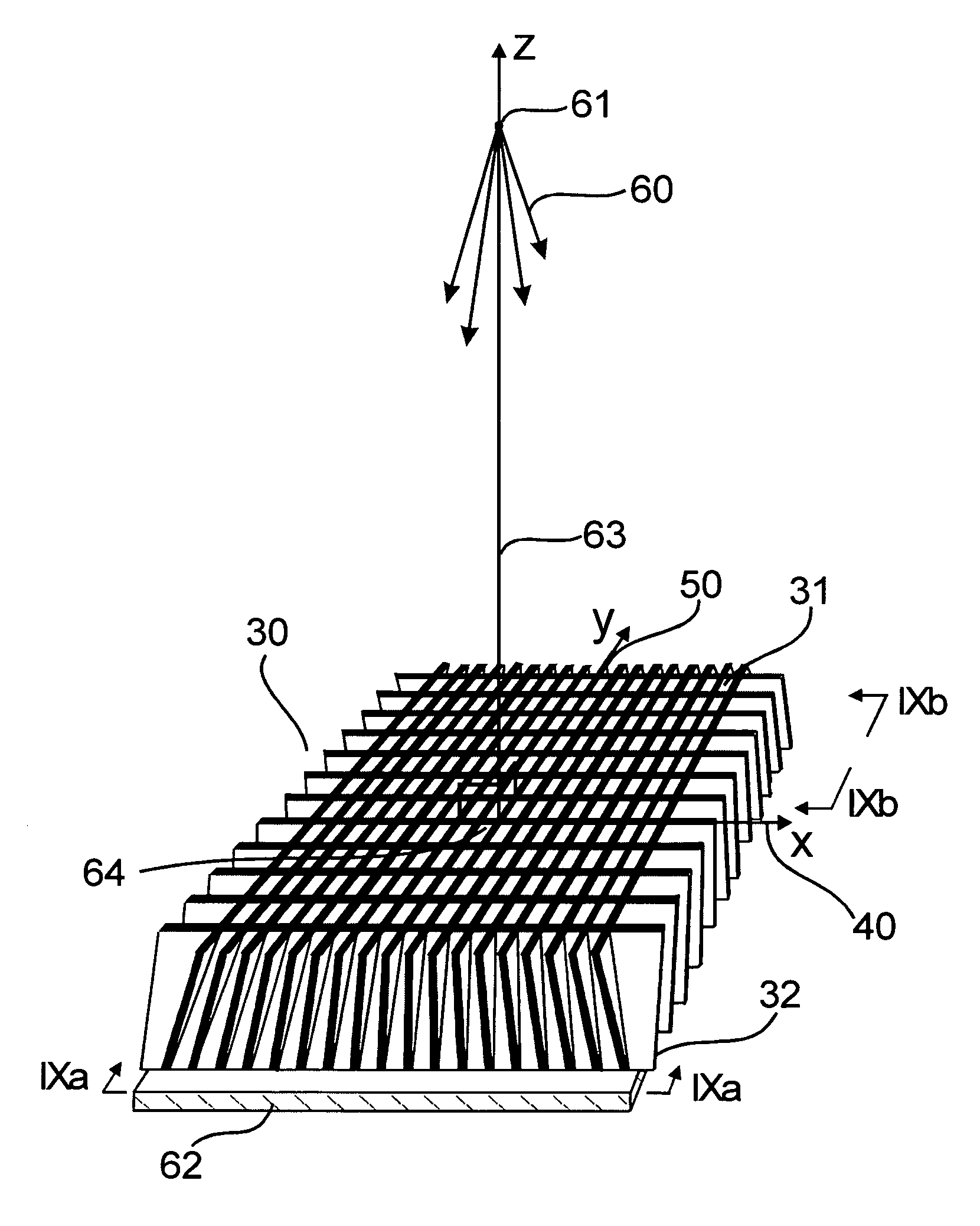
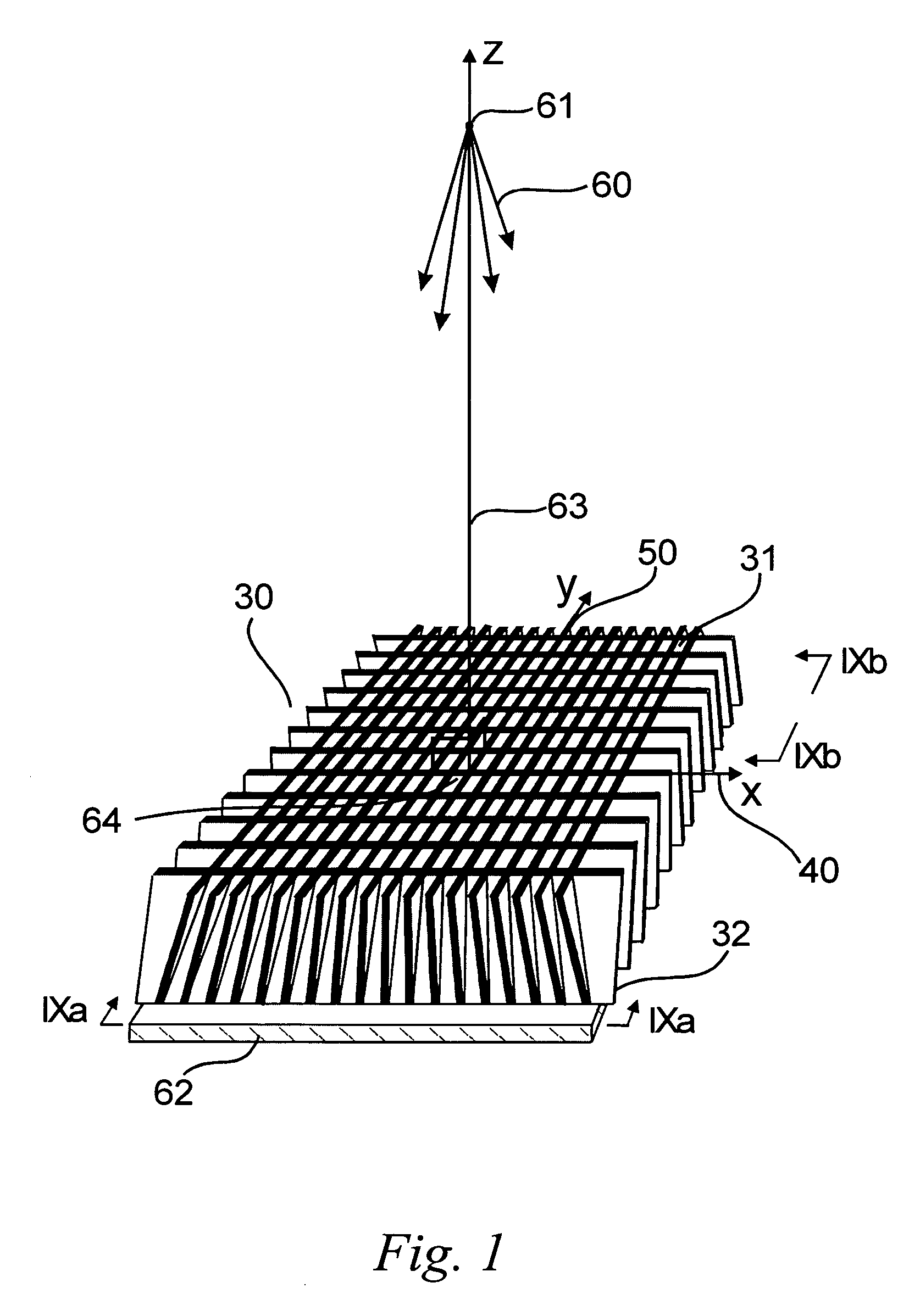
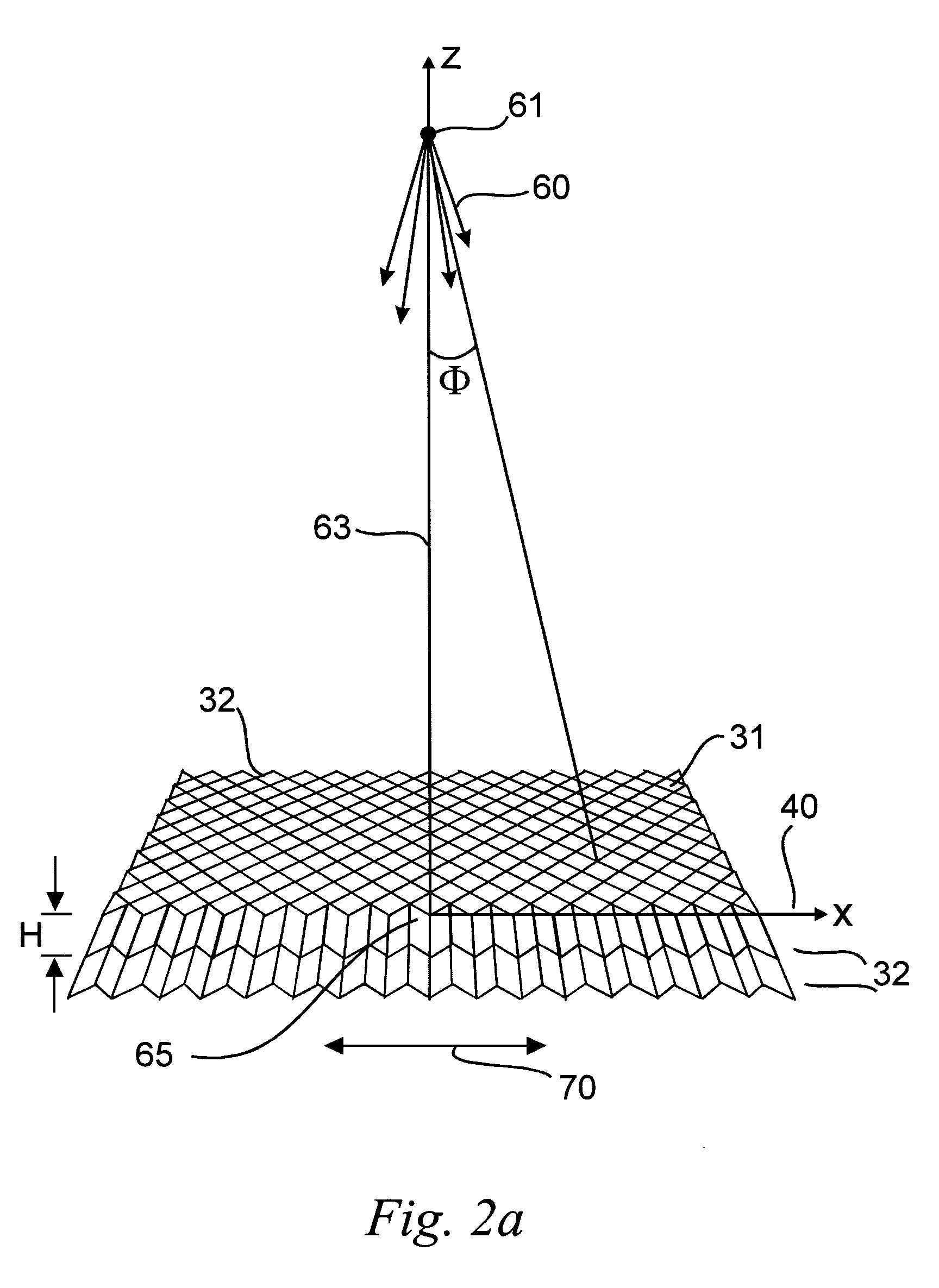
[0097] The present invention provides designs, methods and apparatuses for making large area, two-dimensional, high aspect ratio, grids, collimators, grid / scintillators, collimator / scintillators, x-ray filters and other such devices, with focused walls, defocused walls, variable focus walls, parallel walls and other such orientations, as well as similar designs, methods and apparatuses for all electromagnetic radiation applications. Referring now to the drawings, FIG. 1 shows a schematic of a section of an example of a two-dimensional grid or collimator 30 produced in accordance with an embodiment of a method of the present invention. The method of grid manufacture described here is different from the embodiment of the invention, as described in more detail in U.S. Pat. Nos. 5,949,850 and 6,252,938 referenced above, the entire contents of both being incorporated herein by reference

A. X-Ray Imaging

[0098] In FIG. 1, the x-ray propagates out of a point source 61 with a conical spread...


PUM

PropertyMeasurementUnit
energyaaaaaaaaaa
aspect ratioaaaaaaaaaa
angleaaaaaaaaaa

Abstract

Grids and collimators, for use with electromagnetic energy emitting devices, include at least a metal layer that is formed, for example, by electroplating / electroforming or casting. The metal layer includes top and bottom surfaces, and a plurality of solid integrated walls. Each of the solid integrated walls extends from the top to bottom surface and has a plurality of side surfaces. The side surfaces of the solid integrated walls are arranged to define a plurality of openings extending entirely through the layer. At least some of the walls also can include projections extending into the respective openings formed by the walls. The projections can be of various shapes and sizes, and are arranged so that a total amount of wall material intersected by a line propagating in a direction along an edge of the grid is substantially the same as another total amount of wall material intersected by another line propagating in another direction substantially parallel to the edge of the grid at any distance from the edge. Methods to fabricate these grids using copper, lead, nickel, gold, any other electroplating / electroforming materials, metal composites or low melting temperature metals are described.

Description

[0001] This application is a continuation in part of U.S. patent application Ser. No. 11 / 188,210 which is a continuation of U.S. patent application Ser. No. 10 / 060,399, which_claims benefit under 35 U.S.C. § 119(e) from U.S. Provisional Patent Application Ser. Nos. 60 / 265,353 and 60 / 265,354, both filed on Feb. 1, 2001, the entire contents of all of these documents being incorporated herein by reference. CROSS-REFERENCE TO RELATED APPLICATIONS AND PATENT [0002] Related subject matter is disclosed in U.S. patent application Ser. No. 09 / 459,597, filed on Dec. 13, 1999, in U.S. patent application Ser. No. 09 / 734,761, filed Dec. 13, 2000, and in U.S. Pat. No. 5,949,850, the entire contents of all of these documents are expressly incorporated herein by reference.BACKGROUND OF THE INVENTION [0003] 1. Field of the Invention [0004] The present invention relates to a method and apparatus for making focused and unfocused grids and collimators that are stationary or movable to avoid grid shadow...

Claims


Application Information

Patent Timeline
Patent Type & Authority Applications(United States)
IPC IPC(8): B29C39/10B29C69/00B29C70/84
CPCG21K1/025
Inventor TANG, CHA-MEIMAKAROVA, OLGA V.AMSTUTZ, PLATTE T. IIIYANG, GUOHUA
Owner CREATV MICROTECH
Learn More