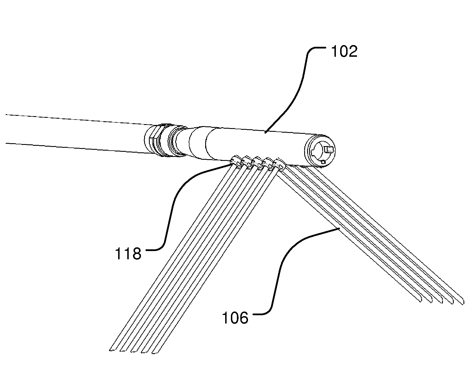
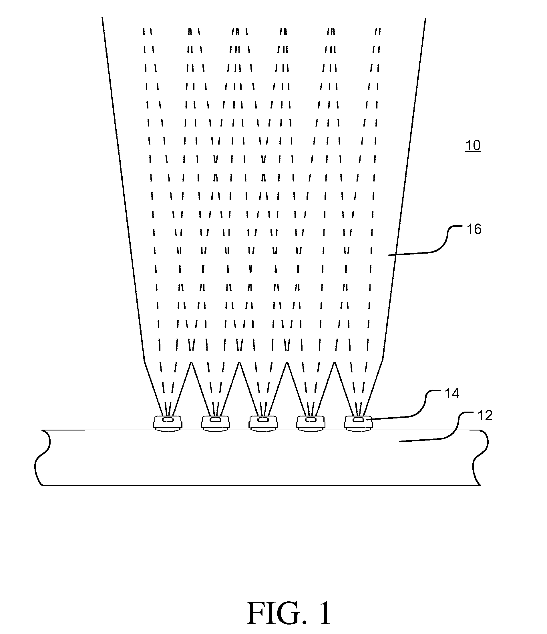
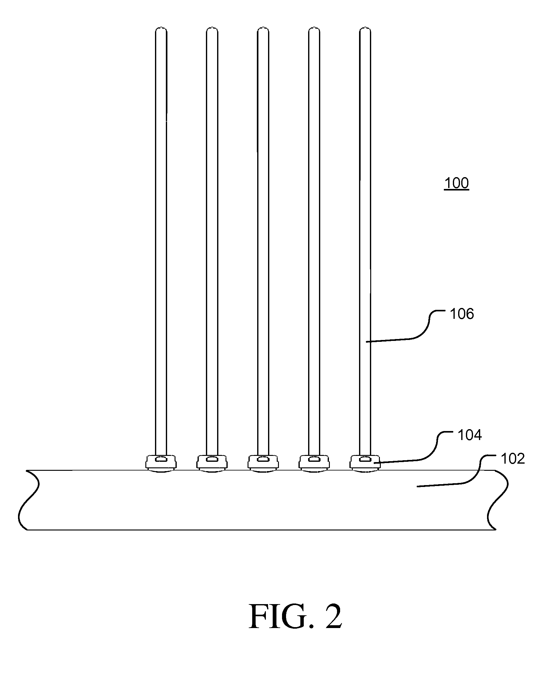
[0020]Example embodiments of the invention include, for example, low-pressure sludge removal methods which reduce the lateral scattering of dislodged sludge into areas that have already been cleaned, thereby increasing the sludge removal efficiency relative to conventional high-pressure lancing techniques. As a consequence, equivalent or improved removal of mobile sludge and / or other loosely bound debris can be achieved in fewer passes, in less time and without the hazards and specialized equipment associated with high-pressure lancing techniques.
[0021]Example embodiments of the invention include, for example, a range of apparatus that may be configured for practicing low-pressure sludge removal methods according to the invention. With respect to nuclear applications, for example, the low-pressure operation of the apparatus allows for installation completely within the
containment building. Conversely, the conventional high-pressure lancing techniques typically require the staging of high-pressure pumps,
filtration equipment, and a majority of the recirculation lines outside the
containment building. The ability to install required equipment completely inside the containment building further reduces time commitment and logistical support required during setup, operation, and teardown of the low-pressure sludge removal apparatus according to the invention.
[0023]As a result, the low-pressure sludge removal method of the current invention can be applied prior to these chemical and mechanical cleaning techniques in order to quickly and efficiently remove piles of soft, highly mobile sludge, and thereby enhance the effectiveness of these subsequent chemical and mechanical cleaning techniques. Conventional high-pressure lancing techniques have typically not been performed prior to the chemical and mechanical cleaning techniques discussed above due to the longer
application time required and the reduced compatibility of high-pressure lancing equipment (e.g., pumps,
filtration and recirculation equipment, etc.) with the recirculation systems used during these chemical and mechanical cleaning processes.
[0024]As yet an additional consequence of the foregoing object, the opposing nozzles used in the low-pressure sludge removing apparatus can be separated by an angle of less than 180°, which facilitates continuous cleaning operation on both sides of the no-tube lane. In contrast, opposing nozzles are typically separated by 180° in apparatus used during conventional high-pressure lancing techniques, such that reaction forces associated with the opposing nozzles offset, and no excessive lift force is imposed on the lance. Unfortunately, this conventional design typically directs the high-pressure water jets provided on one side of the no-tube lane away from the tube sheet while cleaning is being performed on the other.
[0029]For those instances in which the nozzles are provided on at least two cleaning fluid distribution channels, the rotating and / or oscillating units may be operated independently and / or in a synchronized manner to increase the efficiency of the cleaning process. For example, two or more rotating or oscillating units may be arranged in a vertical configuration with their movements synchronized to provide a coordinated initial wash and a secondary wash down a single intertube lane and thereby increase the efficiency of the cleaning process.
[0035]Variations of these basic methods according to example embodiments of the inventions may further include ejecting the cleaning solution from the coherent flow nozzles at a pressure of, for example, no more than about 2.1 MPa and at a flow rate of, for example, 15 liters / min. or more. Example embodiments of methods according to the invention may also include steps and mechanisms for aligning the coherent flow nozzles with the intermember lanes by detecting at least one of the intermember lane and a member adjacent the intermember lane using a sensor selected from a group consisting of optical sensors, mechanical sensors, ultrasonic sensors and capacitive sensors. The step of aligning the coherent flow nozzles with the intermember lanes may also include adjusting a separation spacing between adjacent coherent flow nozzles to correspond to a characteristic
pitch defined by the
regular array. Depending on the configuration of the vessel, additional nozzles, providing either conventional or coherent flow, may be arranged to promote a circumferential flow along at least a portion of the periphery of the
heat exchanger and / or steam generator vessel that helps direct cleaning streams exiting the tube array and the associated
silt and debris toward a removal point, typically a vacuum port, for removing the cleansing solution and any entrained or dissolved
silt or debris from the steam generator.


