Method and System for Forming a Non-Circular Borehole

Inactive Publication Date: 2008-04-24
POTTER DRILLING
View PDF28 Cites 79 Cited by
  • Summary
  • Abstract
  • Description
  • Claims
  • Application Information

AI Technical Summary

Benefits of technology

[0018] A substantially non-circular hole may help stabilize the well bore and prevent break outs. A substantially non-circular hole may also facilitate the installation or operation of a system, such as in the installation of piping for ground source heat pumps. A substantially elliptical hole provides an improved geometry for heat exchange in the ground source heat pump piping loops while also enabling a much faster and more efficient drilling that does not suffer from the shortcomings of the prior techniques.
[0019] In one aspect the present invention provides a system and method for creating shaped drilling holes in rocks especially for the intention of stabilizing the wellbore. The system can create an elliptical shaped hole that intentionally reduces the stresses in the formation around the bore, limiting uncontrolled break-out. Break-out is a process in which rock breaks from the wall of the wellbore, creating a non-circular and substantially elliptical cross-section, often with the longer axis in a substantially horizontal orientation, in order to relieve the stresses in the formation around the well-bore. Break-out may be particularly severe in significantly horizontal or non-vertical portions of the wellbore. Breakout can be caused by significant non-uniform stress concentration in the unsupported borehole resulting in localized shear failure at two opposite nodes in a direction normal to the main stress direction. Once the break-out occurs, the borehole has a more stable geomet

Problems solved by technology

Break-out may be particularly severe in significantly horizontal or non-vertical portions of the wellbore.
Breakout can be caused by significant non-uniform stress concentration in the unsupported borehole resulting in localized shear failure at two opposite nodes in a

Method used


Image

  • Method and System for Forming a Non-Circular Borehole
  • Method and System for Forming a Non-Circular Borehole
  • Method and System for Forming a Non-Circular Borehole

Examples


Embodiment Construction

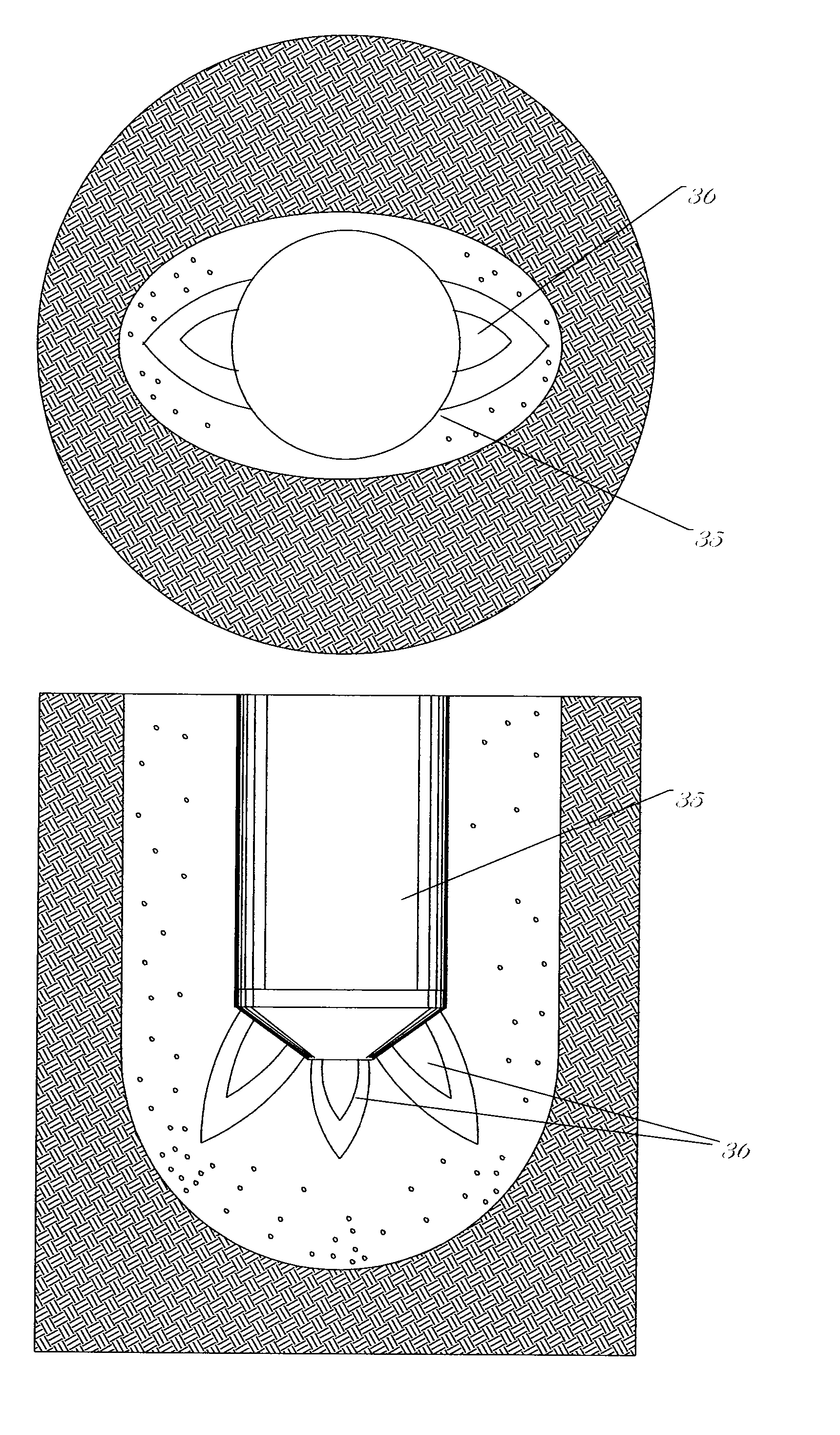
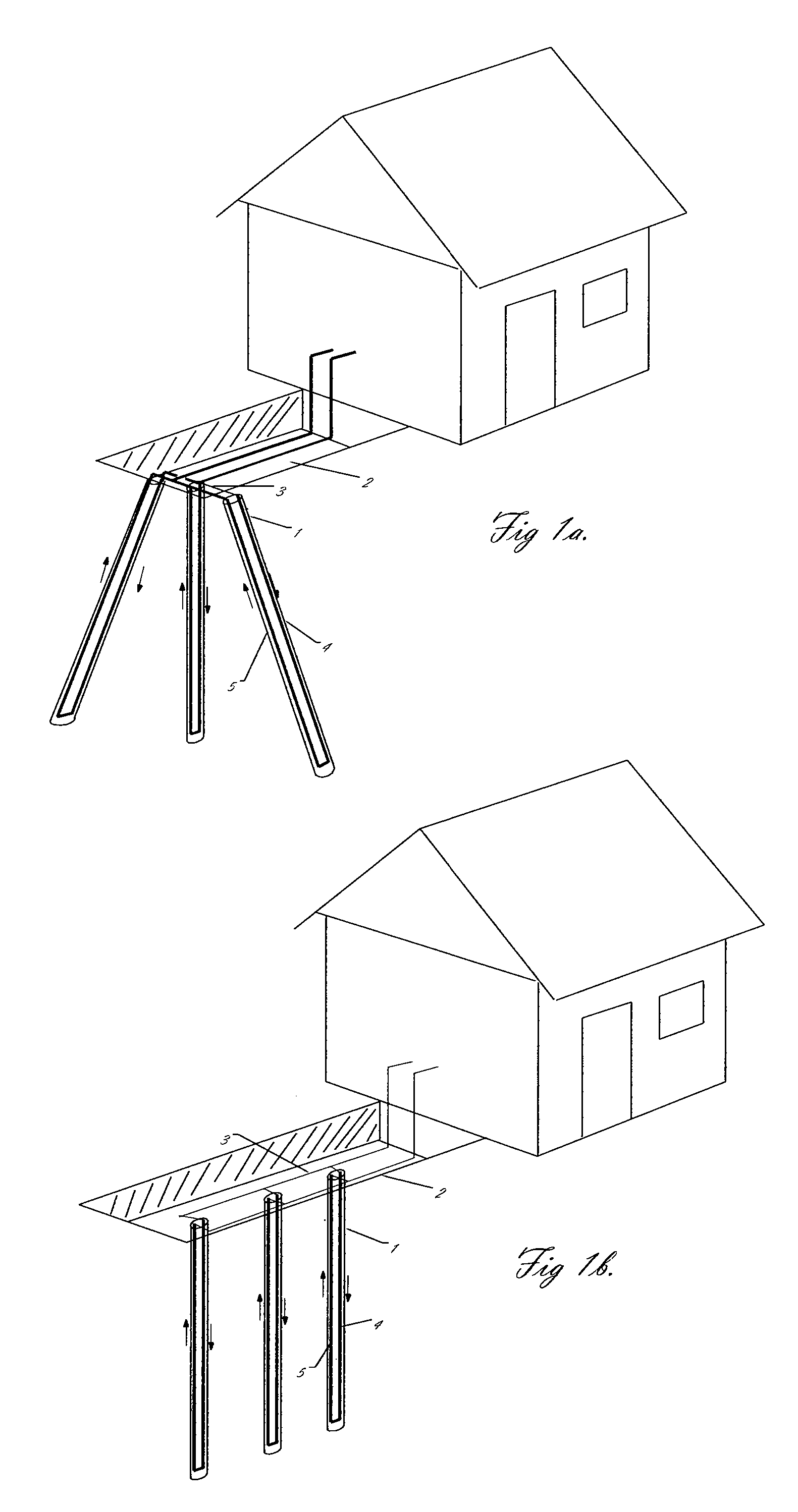
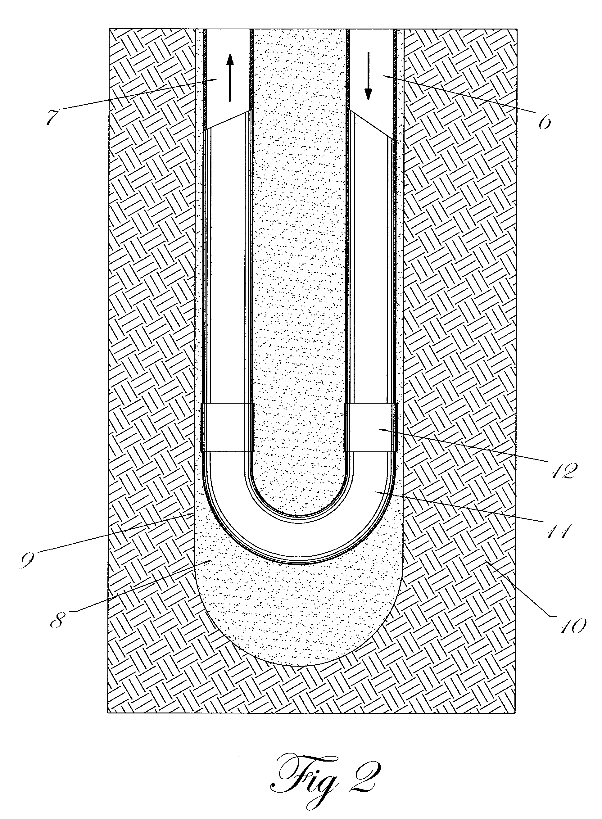
[0039]FIGS. 1a and 1b show the general layout of a geothermal heat pump system which is one such system where oval (e.g., non-circular) boreholes may be beneficial. It should be noted that there exist a number of different ways for locating the boreholes in such a system, and that the general layout of the hole orientation is not critical to the disclosed embodiments of the present invention. In the particular version shown, the heat exchange drill holes are oriented outward from a more or less central point in an excavated trench 2 where the heat exchanger tubes are connected together into a manifold system 3. The out-flowing 4 and in-flowing 5 tubes or pipes are connected to the manifold system 3. The holes are directed from substantially central location to simplify the attachment of the flow tubes to a manifold and to minimize the damage to the terrain around the drill site. A trench is typically used to hide the connection holes and tubing. The flow tubes are typically connecte...


PUM


Abstract

System and methods for creating shaped, non-circular boreholes in rocks especially for use with geothermal heat pump applications and for increasing wellbore support in applications such as horizontal oil and gas drilling are described. The systems and methods when applied to geothermal heat pumps create an elliptical shaped hole that is optimized for placing heat transfer tubes with a minimum of grout used. The significantly reduced cross-sectional area of the elliptical borehole also increases the overall drilling rate in rock and especially in hard rocks. In horizontal hard-rock drilling, creation of a horizontal non-circular borehole or modification of a circular borehole to a non-circular geometry is used to stabilize the borehole prior to casing insertion, and may also allow the use of lower mud pressures improving drilling rates. The system uses a non-contacting drilling system which in one embodiment uses a supersonic flame jet drilling system with a movable nozzle that swings between pivot points. In a second embodiment the elliptical shaped hole is created by an abrasive fluid or particle bearing-fluid or air jet drill that moves between pivot points. In another embodiment a non-contacting drill can use dual parallel nutating nozzles that create a pair of overlapping circular holes. The non-circular shaped hole is created by either the high temperature flame or water-particle jet or chemically active fluid jet as it removes rock material by erosion, dissolution and or thermal spalling. Modifications of circular boreholes to a generally elliptical shape can also be done using milling or jetting techniques.

Description

CROSS-REFERENCES TO RELATED APPLICATIONS [0001] This application claims priority to U.S. Provisional Patent Application No. 60 / 786,456, filed Mar. 27, 2006 whose teachings are incorporated herein by reference.BACKGROUND OF THE INVENTION [0002] The present invention relates in general to the formation of intentionally non-circular boreholes. These non-circular boreholes may be shaped for optimized use in a specific system or application, such as underground heat exchange systems, or they may be formed as a means to stabilize the borehole during the drilling, casing, and completion or in operation. [0003] Most conventional and non-conventional drilling techniques are designed to produce boreholes that are substantially circular. In some formations, such as hard rocks with primary stresses oriented vertically, circular boreholes are inherently unstable which might be caused by the non-uniform stress conditions in the rock or from a general weakness in the rock. Once a circular hole is ...

Claims


Application Information

Patent Timeline
IPC IPC(8): E21B7/18
CPCE21B7/001Y02E10/10F03G7/04F24T2010/53F24T10/15
Inventor POTTER, JARED MICHAELPOTTER, ROBERT MARSHALLBASLER, JAMES ROBERTWIDEMAN, THOMAS WALLER
Owner POTTER DRILLING
Why Eureka
Try Eureka