
Thermal management technology for polarizing xenon

a technology of xenon and thermal management, applied in the field of xenon polarization, can solve the problems and reducing the polarization rate of sup>xe at increasingly high laser power, so as to increase the polarization rate and increase the laser power. , the effect of increasing the temperature of the gas mixtur

Active Publication Date: 2008-04-24
UNIVERSITY OF NEW HAMPSHIRE
View PDF25 Cites 9 Cited by
  • Summary
  • Abstract
  • Description
  • Claims
  • Application Information

AI Technical Summary

Benefits of technology

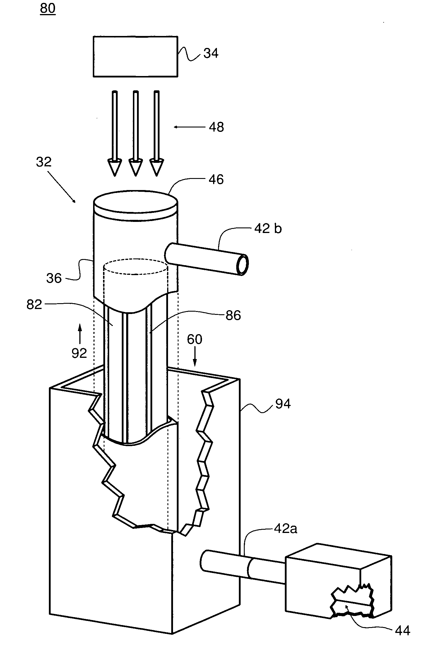
[0010] In contrast to the above-described polarizing apparatus, an improved polarizing apparatus has a heat transfer device for stabilizing the temperature of the flowing gases to a temperature close to the optimal temperature by allowing for the removing of heat from one region of a polarizing cell of the polarizing apparatus. Furthermore, an additional improvement is that a similarly designed extension of that improvement will allow for the simultaneous cooling of the flowing gases and extraction of the alkali vapor while in the presence of the laser. These improvements are enabled by the novel transition from polarizing cells fabricated from glass to a choice of materials that offers higher thermal conductivity.
[0011] It is a purpose of the present invention to stabilize the temperature of the gas mixture in the polarizing cell by conducting heat deposited in the gases to and from a thermal reservoir, allowing the absorbed laser light to increase the rate of production of polarized 129Xe.
[0014] In an embodiment, the partitioning device is a column structure having a plurality of planar walls defining a plurality of channels to allow a gas mixture to pass through and presenting an geometrical obstruction to the propagation of laser light is low.

Problems solved by technology

Unfortunately, there are deficiencies to the above-described polarizing apparatus, particularly when one considers increasing the polarized gas output, including concerns with the temperature of the gas and the effect on the production of polarized 129Xe.
Both strategies result in increased temperature of the gas mixture.
However, it is detrimental to the operation of the polarizer if laser absorption is permitted to cause elevation in temperature significantly beyond that optimal temperature.
Consequently, 129Xe polarization at increasingly high laser power is limited by the resulting elevated temperature of the gas mixture.
Increasing the physical length of the apparatus could become impractical.
Another limitation of the current practice is the choice of material for the polarizing cell.
The low thermal conductivity of glass becomes a limitation to producing larger amounts of hyperpolarized xenon by absorbing more laser power.

Method used


Image

  • Thermal management technology for polarizing xenon
  • Thermal management technology for polarizing xenon
  • Thermal management technology for polarizing xenon

Examples


Embodiment Construction

[0039] An improved polarizing apparatus utilizes a thermally conductive partitioning system in a polarizing cell. In the polarizing region, this thermally conductive partitioning system serves to prevent the elevation of the temperature of the polarizing cell where laser light is maximally absorbed to perform the polarizing process. By employing this partitioning system, increases in laser power of factors of ten or more can be beneficially utilized to polarize xenon. Accordingly, conventional polarizing apparatus and the method of polarizing 129Xe fail to achieve rates of production achieved by the method described below.

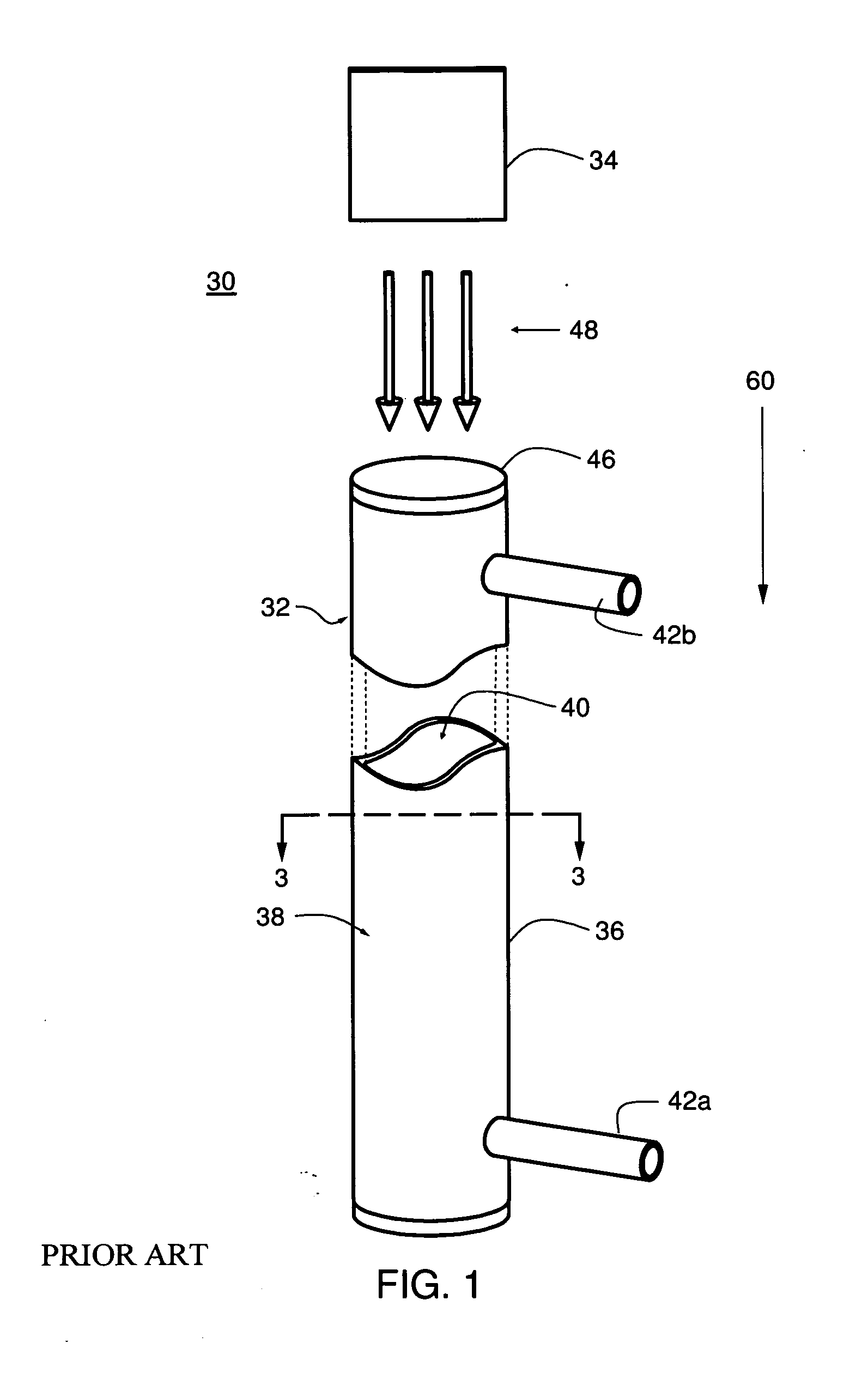
[0040] Referring to FIG. 1, a prior art polarizing apparatus 30 having a polarizing cell 32 and a laser 34 is shown. The polarizing cell 32 has a non-magnetic enclosure 36 having a circular side wall 38 defining an interior 40. The circular side wall 38 has at least two openings, an entrance 42a and an exit 42b for flowing a gas mixture 44 from the entrance 42a to...


PUM


Abstract

A polarizing apparatus has a thermally conductive partitioning system in a polarizing cell. In the polarizing region, this thermally conductive partitioning system serves to prevent the elevation of the temperature of the polarizing cell where laser light is maximally absorbed to perform the polarizing process. By employing this partitioning system, increases in laser power of factors of ten or more can be beneficially utilized to polarize xenon. Accordingly, the polarizing apparatus and the method of polarizing 129Xe achieves higher rates of production.

Description

CROSS-REFERENCE TO RELATED APPLICATIONS [0001] The present application claims the benefit of Provisional Patent Application No. 60 / 846,043 filed Sep. 20, 2006, which is incorporated herein by reference.TECHNICAL FIELD [0002] The present invention relates to polarization of Xenon. More specifically, it relates to a means to increase the rate of polarization of Xenon by using multiple heat exchanger channels. BACKGROUND OF THE INVENTION [0003] Hyperpolarized Xenon (129Xe) is becoming the contrast agent of choice in a broad spectrum of diagnostic protocols. Specifically, hyperpolarized 129Xe offers extraordinary potential as a contrast agent for magnetic resonance imaging (“MRI”). [0004]129Xe is hyperpolarized by spin-exchange optical pumping using a gas mixture of Xe (with natural abundance of 129Xe or enriched in 129Xe), a quenching gas (nitrogen or hydrogen), and optional buffer gas (typically helium). In addition to these gases, the flowing gas mixture acquires a vapor of alkali me...

Claims


Application Information

Patent Timeline
Patent Type & Authority Applications(United States)
IPC IPC(8): H05H3/02H05H6/00
CPCH05H6/005G21K1/16Y10S62/923Y10S62/925
Inventor HERSMAN, F. WILLIAM
Owner UNIVERSITY OF NEW HAMPSHIRE
Learn More