
Power Supply Apparatus With Function of Detecting Abnormality of Current Sensor

a technology of current sensor and power supply apparatus, which is applied in the direction of motor/generator/converter stopper, process and machine control, electric devices, etc., can solve the problems of inverter damage, inverter damage, and insufficient load on the inverter, so as to achieve high detection precision, high detection precision, and effective use of processing time of the cpu

Inactive Publication Date: 2008-04-24
TOYOTA JIDOSHA KK
View PDF6 Cites 29 Cited by
  • Summary
  • Abstract
  • Description
  • Claims
  • Application Information

AI Technical Summary

Benefits of technology

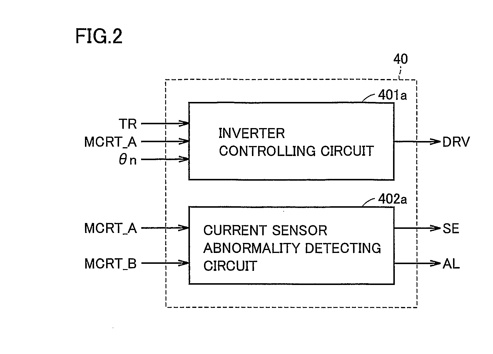
The present invention provides a power supply apparatus with a current sensor that can detect abnormalities quickly and accurately. The apparatus includes a power supply, a drive circuit, and a current sensor abnormality detecting circuit. The current sensor abnormality detecting circuit detects abnormalities in the current sensor by monitoring the current detect value and the current difference between the current detect value and a prescribed threshold value. This allows for the quick detection of abnormalities in the current sensor, which can prevent damage to the drive circuit. The current sensor abnormality detecting circuit can also adjust the prescribed threshold value based on the detected temperature of the circuit element, further improving the accuracy of the detection.

Problems solved by technology

When this overcurrent passes through the inverter, a load corresponding to the magnitude of the current and the time during which the current passes is placed on the inverter, whereby the inverter may be damaged.
However, with this conventional abnormality detecting apparatus, in consideration of preventing erroneous detection, lapse of a certain period is always necessary for determining an abnormality.
When the motor current becomes an overcurrent when the motor output system is abnormal, the load placed on the inverter becomes considerably great proportionally to the certain period, and whereby the inverter may be damaged.
Thus, it cannot be compared with a prescribed threshold value in magnitude accurately.
This increases the period required for determining an abnormality and the load to the inverter.

Method used


Image

  • Power Supply Apparatus With Function of Detecting Abnormality of Current Sensor
  • Power Supply Apparatus With Function of Detecting Abnormality of Current Sensor
  • Power Supply Apparatus With Function of Detecting Abnormality of Current Sensor

Examples


first embodiment

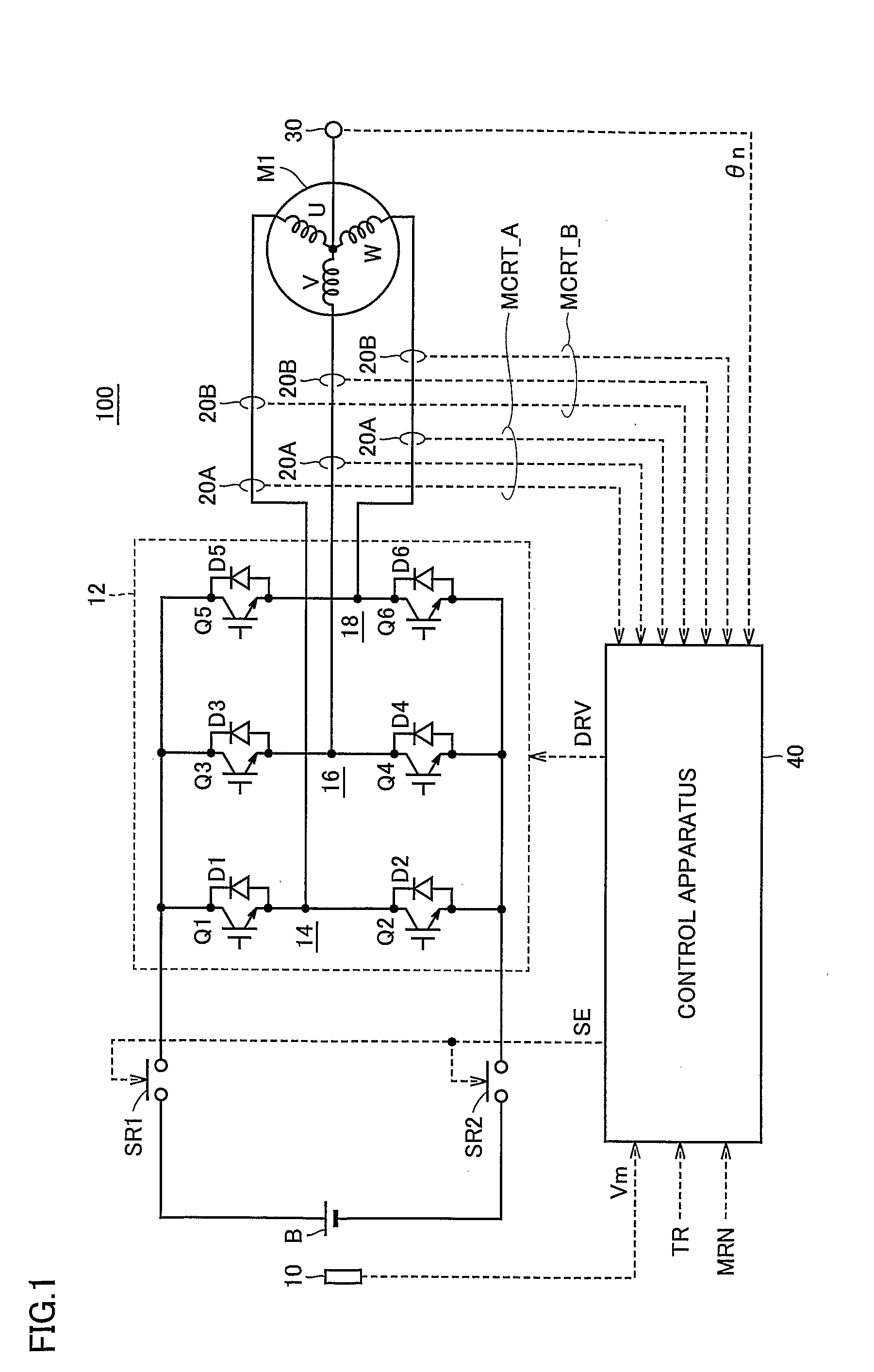
[0048]FIG. 1 is a schematic block diagram of a power supply apparatus according to a first embodiment of the present invention.

[0049] Referring to FIG. 1, a power supply apparatus 100 includes a DC (Direct Current) power supply B, system relays SR1 and SR2, a voltage sensor 10, an inverter 12, current sensors 20A and 20B, a resolver 30, and a control apparatus 40.

[0050] AC motor M1 is a drive motor for generating torque for driving the driving wheels of a hybrid vehicle or an electric vehicle. AC motor M1 has a function of a generator driven by an engine, and also operates as an electric motor to the engine, e.g., to start the engine.

[0051] Inverter 12 is constituted by a U-phase arm 14, a V-phase arm 16 and a W-phase arm 18. U-phase arm 14, V-phase arm 16, and W-phase, arm 18 are provided in parallel between the power supply line and the earth line.

[0052] U-phase arm 14 is constituted by serially connected NPN transistors Q1 and Q2. V-phase arm 16 is constituted by serially con...

second embodiment

[0123]FIG. 8 is a schematic diagram for describing an abnormality detecting operation according to a second embodiment of the present invention.

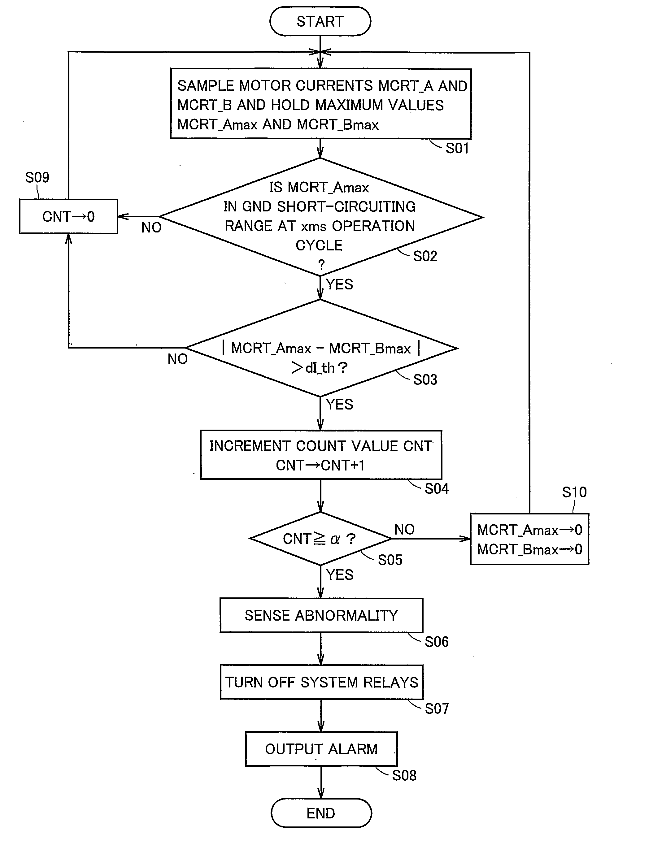
[0124] Referring to FIG. 8, when current sensor 20A is involved with GND short-circuiting abnormality in power supply apparatus 100, motor current MCRT_A forms a current waveform fixed to the GND short-circuiting range as indicated by the solid line. Affected by motor current MCRT_A, motor current MCRT_B forms a current waveform oscillating at a current level higher than a sine wave in a normal state. Details of the current waveforms are as described above with reference to FIG. 5.

[0125] Here, as described above, GND short-circuiting abnormality of current sensor 20A must be detected in a short period, since high motor current MCRT_B continuously passing through inverter 12 places excessive load on inverter 12. On the other hand, if the abnormality determining period is reduced further, motor current MCRT_B with a temporary high current le...


PUM


Abstract

A current detector (60) samples a motor current (MCRT_A) from a controlling sensor and a motor current (MCRT_B) from a monitoring sensor, and holds respective motor current maximum values (MCRT_Amax, MCRT_Bmax) at each prescribed operation cycle. An abnormality determiner (62a) detects that the motor current maximum value (MCRT_Amax) is in GND short-circuiting range and that the current difference between the maximum values exceeds a prescribed threshold value at each of successive operation cycles, to thereby determine an abnormality of the controlling sensor. Then, the abnormality determiner (62a) generates a detect signal (DET) specifying the current sensor abnormality and outputs it to a relay driver (64) and an alarm (66). Relay driver (64) receives the detect signal (DET) and generates a signal (SE) to turn off a system relay. The alarm (66) generates a signal (AL) and outputs it to display means arranged outside a power supply apparatus.

Description

TECHNICAL FIELD [0001] The present invention relates to a power supply apparatus, and particularly to a power supply apparatus with a function of detecting an abnormality of a current sensor, which detects a current passing through a drive circuit incorporated in the power supply apparatus. BACKGROUND ART [0002] In recent years, hybrid vehicles and electric vehicles are receiving attention as environment-friendly vehicles. A hybrid vehicle includes as its motive power source, in addition to a conventional engine, a DC Direct Current) power supply, an inverter, and a motor driven by the inverter. Specifically, the vehicle is powered by driving the engine, as well as by converting a DC voltage from the DC power supply into an AC (Alternating Current) voltage by the inverter so that the converted AC voltage is used to drive the motor. [0003] An electric vehicle is powered by a DC power supply, and inverter and a motor driven by the inverter. [0004] Generally, in such hybrid vehicle and...

Claims


Application Information

Patent Timeline
Patent Type & Authority Applications(United States)
IPC IPC(8): H02H7/08H02P27/06B60L3/00G01R19/00G01R31/00G01R31/34G01R35/00
CPCG01R31/42H02H1/0007H02P29/022H02H7/0844H02H3/05H02P29/032
Inventor OCHIAI, KIYOE
Owner TOYOTA JIDOSHA KK
Learn More