Controlling the bandwidth of an analog filter

a bandwidth control and analog filter technology, applied in the field of analog filters, can solve the problems of static/transient power mask performance, static sensitivity, sensitivity, adjacent channel leakage ratio,

Active Publication Date: 2008-04-24
APPLE INC
View PDF23 Cites 24 Cited by
  • Summary
  • Abstract
  • Description
  • Claims
  • Application Information

AI Technical Summary

Problems solved by technology

Variations in the bandwidth of the analog filter may lead to significant performance degradation in both receive and transmit signal paths of the wireless device.
In the receive signal path, variations in the bandwidth of a baseband analog filter leads to performance degradation in static sensitivity, sensitivity in the presence of interferers, receiver third-order intercept point, anti-aliasing performance and error vector magnitude (EVM).
In the transmit signal path, variations in the bandwidth of the baseband analog filter leads to performance degradation in the EVM, adjacent channel leakage ratio, and static/transient power mask performance.
The tracking accuracy of some known methods is limited due to a variance in a pseudorandom calibration signal and due to long term averaging needed for the tracking loop to converge.
The total calibration time of known methods that use a pseudorandom calibration signal is approximately 10-msec, which is disadvantageously long.
In spite of the long calibration time of known methods, it is difficult for known methods to achieve high calibration accuracy because of a variance in the pseudorandom signal.
However, precise matching is not always possible becau

Method used


Image

  • Controlling the bandwidth of an analog filter
  • Controlling the bandwidth of an analog filter
  • Controlling the bandwidth of an analog filter

Examples


Embodiment Construction

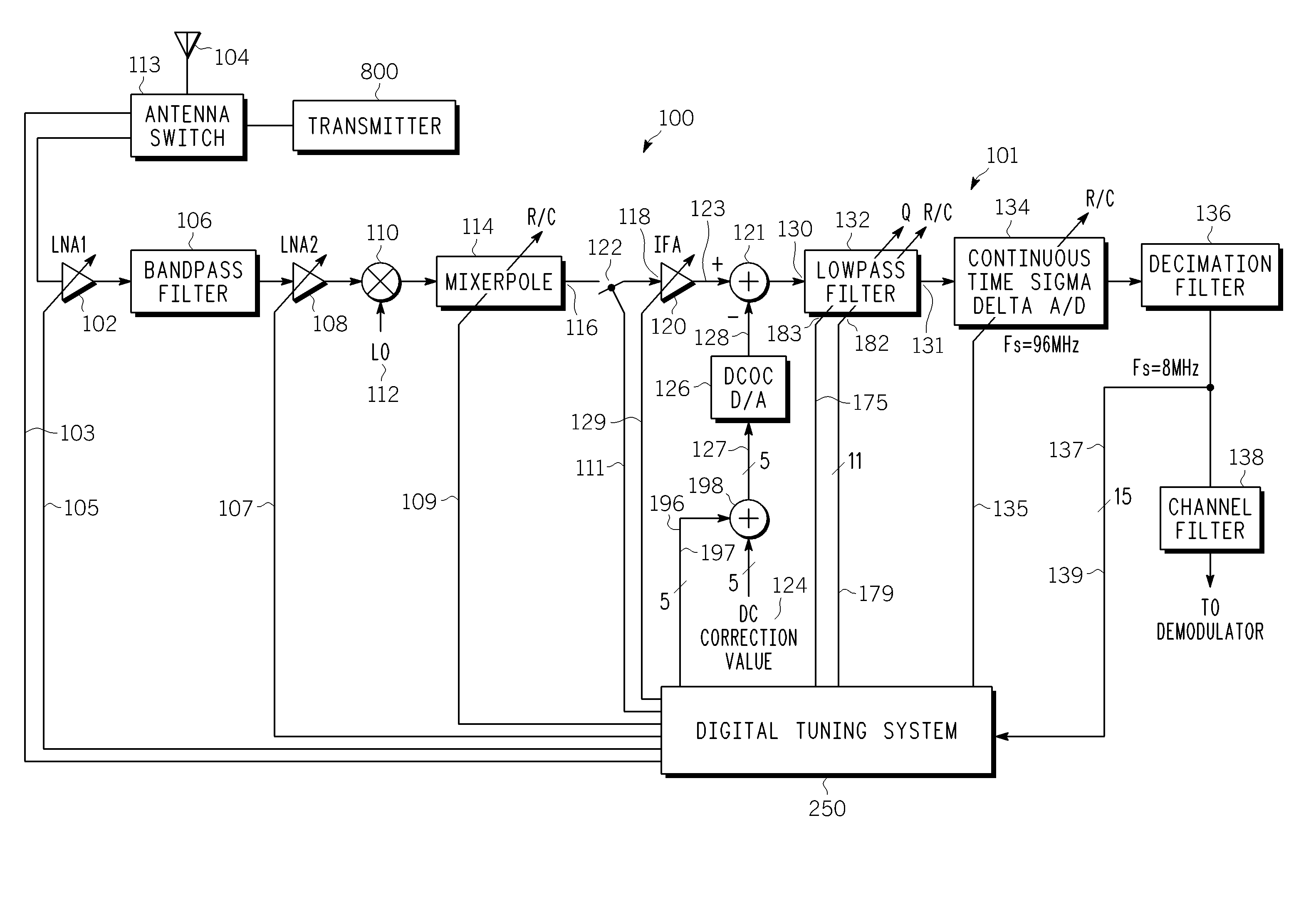
[0020]FIG. 1 is a simplified functional block diagram of a transceiver 100, including a portion of a zero-IF, or baseband, receiver 101. In an exemplary embodiment, the transceiver 100 is a mobile, or wireless, telephone. The receiver 101 includes a first low noise amplifier (LNA) 102 coupled to an antenna 104 through an antenna switch 113, a bandpass filter 106 coupled to the first LNA, a second LNA 108 coupled to the bandpass filter, a mixer 110 coupled to a local oscillator 112 and to the second LNA, and a mixer pole 114 coupled to the mixer. The mixer pole 114 has an output 116 that is coupled to an input 118 of a baseband, or intermediate frequency, amplifier (IFA) 120 via a switch 122. The IFA 120 has an output 123. A digital DC correction value 124 is inserted into an input of a DC offset correction (DCOC) digital-to-analog (D / A) converter 126 via a five-bit coupling 127. The output signal of the DCOC D / A converter 126 is a dcoc_dac_out 128. As more fully explained hereinbelo...


PUM


Abstract

A digital tuning system (250) for changing a cutoff frequency of an analog filter (132) includes digital synthesizers (292 and 294) for producing a two-tone calibration signal (196) applied to an input of the filter after a quality factor of the filter is increased. The filter includes at least one R/C circuit with two resistors (304 and 306) for changing the quality factor and arrays (308 and 310) of capacitors for changing the cutoff frequency. The amplitude of the magnitude responses (409 and 411) of the filter to each tone (405 and 407) is measured by a two discrete Fourier transform single-frequency bin power detection circuits (253 and 254) while the filter is sequenced through a plurality of capacitance settings. An optimal capacitance for the R/C circuit is selected by comparing, to a pre-selected value, a difference between the responses of the filter to each tone, for each capacitance setting.

Description

BACKGROUND OF THE INVENTION[0001]1. Field of the Invention[0002]This invention generally relates to analog filters, and more particularly to tuning an analog filter using a digital circuit.[0003]2. Description of the Related Art[0004]Continuous-time, or analog, filters are often used in wireless devices such as cellular telephones. Typically, the analog filter and other circuits comprising a receiver or a transmitter are on a single integrated circuit manufactured using complementary metal oxide semiconductor (CMOS) technology. The analog filter comprises components, including resistors and capacitors, that affect a bandwidth of the analog filter. Integrated circuit manufacturing or fabrication processes may cause the actual value of such components to vary by as much as 30% from their nominal value, which may cause bandwidth variations by as much as 50%. The bandwidth variations may also be caused by temperature or voltage changes. Variations in the bandwidth of the analog filter m...

Claims


Application Information

Patent Timeline
IPC IPC(8): H04B1/06H04B1/10
CPCH03H11/1217H03H11/1256H04B1/30H03H11/1291H03H2210/012H03H2210/015H03H2210/025H03H2210/036H03H11/04H04B1/66
Inventor RAHMAN, MAHIBURPARKES, JOHN J.RICHES, JAMES J.
Owner APPLE INC
Why Eureka
Try Eureka