Thrombectomy and soft debris removal device

a soft debris and thrombosis technology, applied in the field of medical instruments, can solve problems such as partial or total occlusion of the vessel, and achieve the effects of safely removing obstructions, restoring patency to the vessel, and reducing associated blood loss

Active Publication Date: 2008-04-24
SPECTRANETICS
View PDF98 Cites 67 Cited by
  • Summary
  • Abstract
  • Description
  • Claims
  • Application Information

AI Technical Summary

Benefits of technology

[0026] It is an object of this invention to provide an efficient manner for the removal of obstructions in a vessel or lumen. This is achieved by providing an assembly for debris removal, incorporating an “Archimedes” screw pump to aspirate and clear debris from the body.
[0027] It is another object of the invention to provide a safe manner for the removal of obstructions in a vessel or lumen. This is achieved by providing a device wherein the cutting surfaces are shielded from direct contact with the lumen or vessel wall, and provisions are taken to prevent occlusive material from traveling further away from the site and into the body. Furthermore, provisions are made to minimize associated blood loss in the procedure, both in operation of the device as well as in the duration of time required for the performance of the procedure to restore patency to the vessel.
[0028] It is yet another object of the invention to provide a small diameter wire guided catheter, which can safely remove obstructions in a vessel or lumen which are located at a distance from the path of the guidewire. This is achieved, for example, by providing an e

Problems solved by technology

The clots are formed by aggregations of thrombus and fibrin, resulting in partial or total occlusion of the vessel.
The prior art described does not disclose a device suitable for reaching narrow vasculature or lumens within the body in order to clear occlusive material, the device having shielded cutting elements to protect the vessel wall, the device serving to ensure partial to complete evacuation of t

Method used


Image

  • Thrombectomy and soft debris removal device
  • Thrombectomy and soft debris removal device
  • Thrombectomy and soft debris removal device

Examples


Embodiment Construction

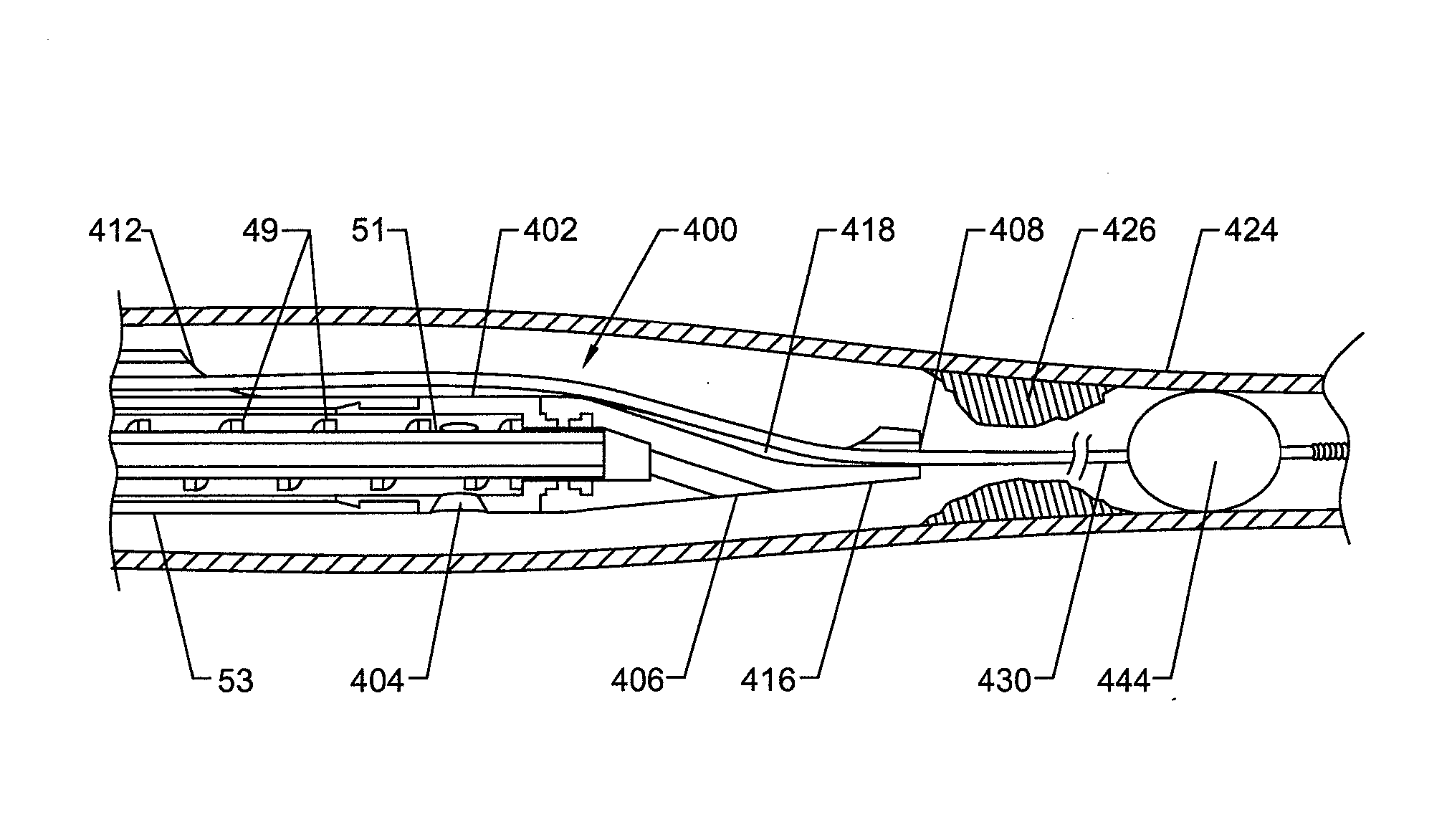
[0051] The present invention provides an assembly having a sufficiently narrow crossing profile (for example, the cross-section of the inserted device at its widest point), and also having adequate flexibility such the invention is capable of operating while flexed and navigating into regions of a body of a living being in order to clear occlusive material, e.g. blood clots or plaque accumulation in a blood vessel or lumen.

[0052] The following description describes the catheter assembly, components and features depicted in the figures, wherein like numbers refer to like components.

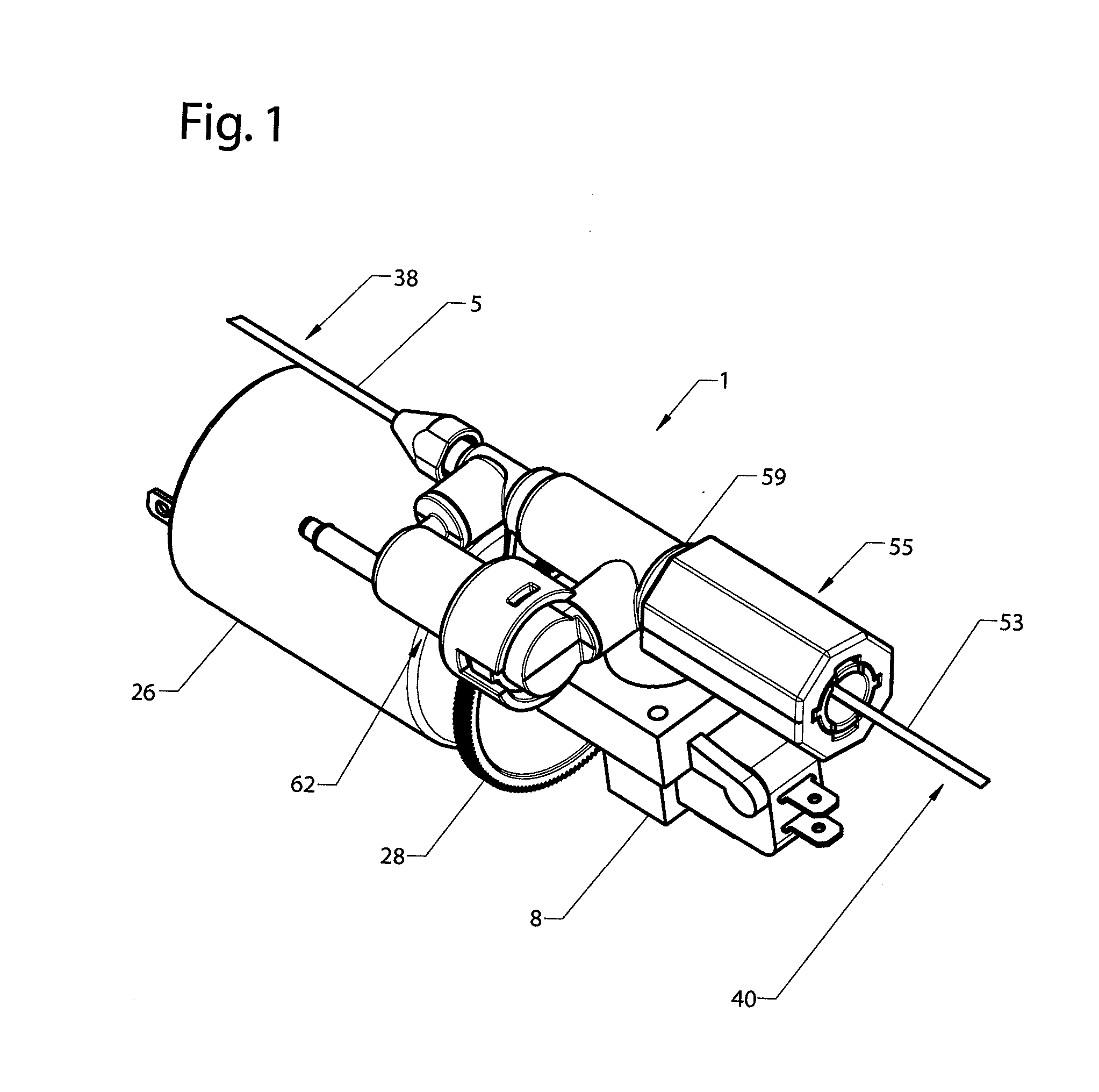
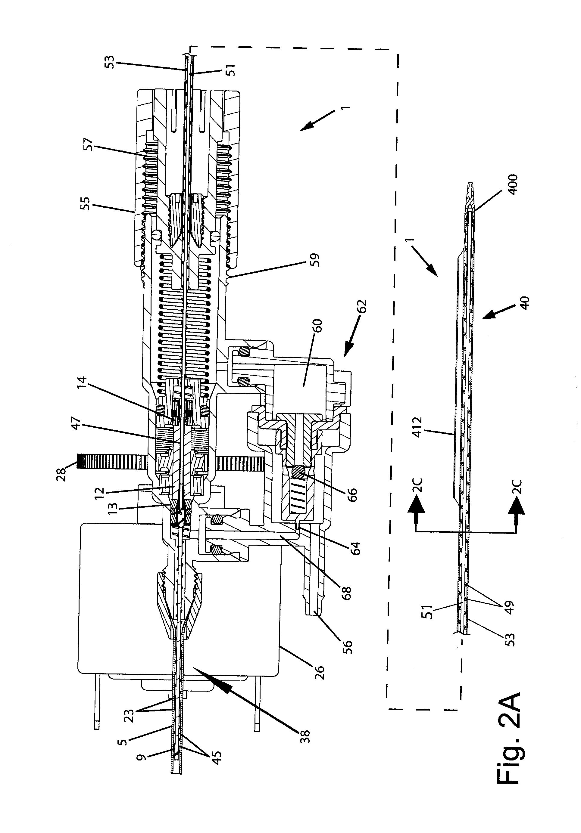
[0053] In one embodiment, the catheter assembly features a pair of rotary helical pumps, the helical pumps serving the function of aspiration and infusate delivery, and may be operated independently by distinct sources of rotary power (e.g., electrical motors, air turbine, hydraulic, etc.). In an embodiment, the rotor for each of the helical pump mechanisms (infusate and aspiration) are operatively coupl...


PUM


Abstract

A device suitable for removing material from a living being is provided, featuring at least an aspiration pump, powered by a motor. The aspiration pump and any optional infusate pump preferably feature a helical pumping mechanism, and operate at a high rate of rotation, thereby ensuring adequate pumping performance and flexibility. The helical pumping mechanism may be a helical coiled wire about a central core tube. The helical coil wire, whether together with, or independent of, the core tube, may be rotated to cause a pumping action. Additionally, a narrow crossing profile is maintained, ensuring that the device may reach more tortuous regions of the vasculature. In one embodiment, the system comprises a wire-guided mono-rail catheter with a working head mounted on a flexible portion of the catheter that can laterally displace away from the guide wire to facilitate thrombus removal. The working head may be operated to separate and move away from the guide wire to come within a closer proximity of the obstructive material to more effectively remove it from the vessel.

Description

CROSS-REFERENCE TO RELATED APPLICATIONS [0001] This patent document is a Continuation-in-Part of copending and commonly owned U.S. patent application Ser. No. 11 / 751,443, filed May 21, 2007, which is a Continuation-in-Part of 10 / 832,830, filed Apr. 27, 2004 in the names of John E. Nash et al. and entitled, “Thrombectomy and Soft Debris Removal Device.” The entire contents of these prior applications are expressly incorporated by reference.BACKGROUND OF THE INVENTION [0002] This application relates generally to medical instruments and methods of use to remove occlusive material from a vessel, duct or lumen within the body of a living being, specifically relating to the removal of thrombus or soft tissue clots from vascular or other lumens. A preferred embodiment more particularly concerns a device useful for clearing lumens relying on a device, incorporating at least one pumping means, to aspirate the debris, thereby clearing a partial or complete blockage of the vessel or lumen. [00...

Claims


Application Information

Patent Timeline
IPC IPC(8): A61B17/22
CPCA61B17/320758A61B2017/320741A61B17/320783A61B2017/320733A61B2017/00685A61B2217/005A61B17/32037A61B2017/22039A61B2017/320766
Inventor NASH, JOHN E.WALTERS, GREGSAURO, DENNIS M.EBERHAROT, MARKFISHER, WILLIAM T.EVANS, DOUGLAS G.
Owner SPECTRANETICS
Why Eureka
Try Eureka