Bore head for microbore operation

a micro-bore and operation technology, applied in the field of bore head, to achieve the effect of facilitating the coupling and uncoupling of drill rods

Inactive Publication Date: 2008-05-01
DAVIES RODNEY JOHN
View PDF37 Cites 18 Cited by
  • Summary
  • Abstract
  • Description
  • Claims
  • Application Information

AI Technical Summary

Benefits of technology

[0017] The drive from the motor to the bore head may include a universal coupling. The coupling is preferably sited close to the carriage. A universal coupling inside the bore head allows the cutter shaft to waggle and respond to steering forces selected by the oper...

Problems solved by technology

While the operator had a good view of the laser spot on the target,...

Method used


Image

  • Bore head for microbore operation
  • Bore head for microbore operation
  • Bore head for microbore operation

Examples


Embodiment Construction

Platform

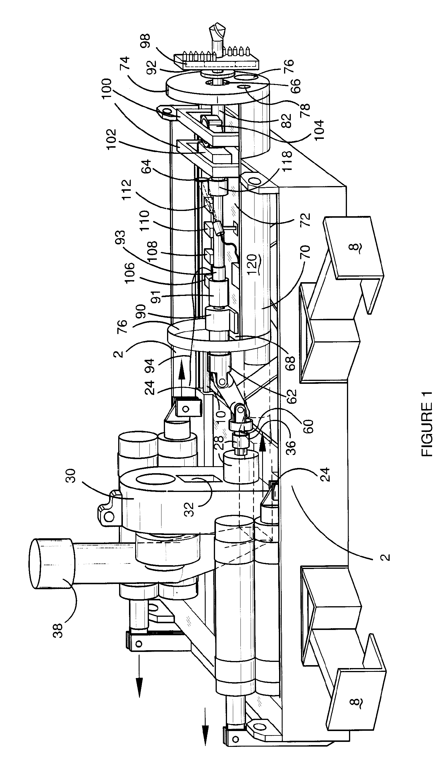
[0027] Referring now to the drawings, especially FIGS. 1 and 2, the platform bearers 2 are mutually connected by zig zag ties 4. The bearers are of C-shaped cross-section and are directionally positioned in the pit 6 by L-section thrusters 8. The bearers each support a stainless steel rail 10 of keyhole section. Carriage 12 extends across the width of the platform with a floor 14 on which is mounted a hydraulic drive assembly 16.

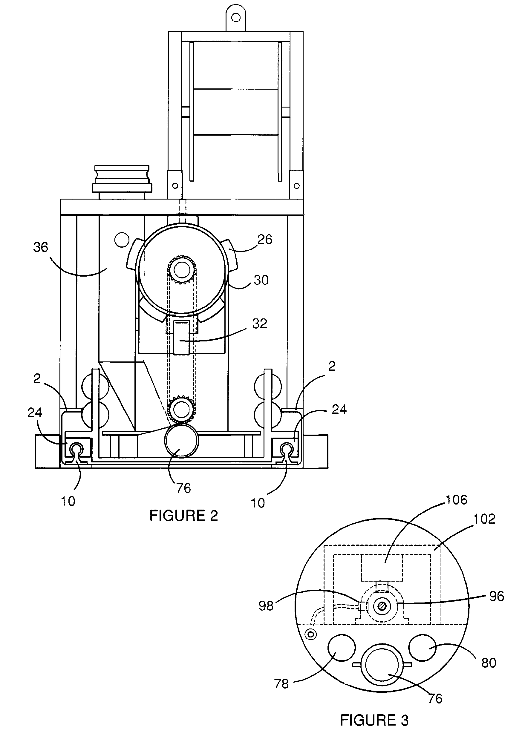
[0028] The front end of the carriage has an upstanding pair of brackets 18. A corresponding pair of brackets 20 extends from the rear of the platform. The cylinders of a pair of carriage rams 22 are connected side by side to the carriage. The connecting rods point in mutually opposite directions and react against brackets 18 and 20 thereby doubling the stroke of the rams. The platform rides on slides 24 (FIG. 2) which embrace the rails and ensure accurate linear motion.

[0029] The drive assembly comprises hydraulic motor 26 which delivers rotation ...


PUM


Abstract

Boring apparatus for drilling laser guided microbore tunnels uses a liquid stream to remove soil as slurry and an airstream to conduct the slurry away from the bore head. The cylindrical head houses a drill shaft steered by a pair of remotely controlled rams according to the position of a laser spot on a target fixed close to the end of the drill shaft. Small arcuate steering movements shift the cutter up and down through a first ram alongside the shaft working through a linkage. Side to side steering is provided by a second ram acting directly on the shaft. The components are mounted on an axial base wall which gives repair access and camera view of the target. A drilling platform has rams for advancing the cylindrical head.

Description

CROSS-REFERENCE TO RELATED APPLICATION(S) [0001] This application is a continuation-in-part of U.S. patent application Ser. No. 11 / 566,306 filed Dec. 4, 2006, which is a continuation-in-part of U.S. patent application Ser. No. 10 / 622,710 filed Jul. 17, 2003, the entire disclosure of each of which is hereby incorporated by reference herein for all purposes.FIELD OF THE INVENTION [0002] This invention concerns apparatus for drilling laser guided microbore tunnels and particularly a bore head for such apparatus. BACKGROUND OF THE INVENTION [0003] In our application Ser. No. 11 / 566,306 being a c-i-p of Ser. No. 10 / 622,710, we describe microbore operations which create horizontal bores 2-6 m below ground for the introduction of pipes from 300-600 mm in diameter. These bring services such as sewerage, mains water, mains gas and the like to buildings where the runs are short but perhaps crowded such as suburban housing or industrial estates. [0004] The operation is preceded by the selectio...

Claims


Application Information

Patent Timeline
IPC IPC(8): E21B10/60E21B4/00
CPCE21D9/13E21D9/004
Inventor DAVIES, RODNEY JOHN
Owner DAVIES RODNEY JOHN
Why Eureka
Try Eureka