Electric power generating apparatus for movement type equipment and self-generation system having the same
a technology of electric power generation and movement type equipment, which is applied in the direction of electrical equipment, piezoelectric/electrostrictive/magnetostrictive devices, piezoelectric/electrostriction/magnetostriction machines, etc., can solve the problems of device not operating, battery replacement is required, energy conversion efficiency is low, etc., and achieves high energy conversion efficiency
- Summary
- Abstract
- Description
- Claims
- Application Information
AI Technical Summary
Benefits of technology
Problems solved by technology
Method used
Image
Examples
first embodiment
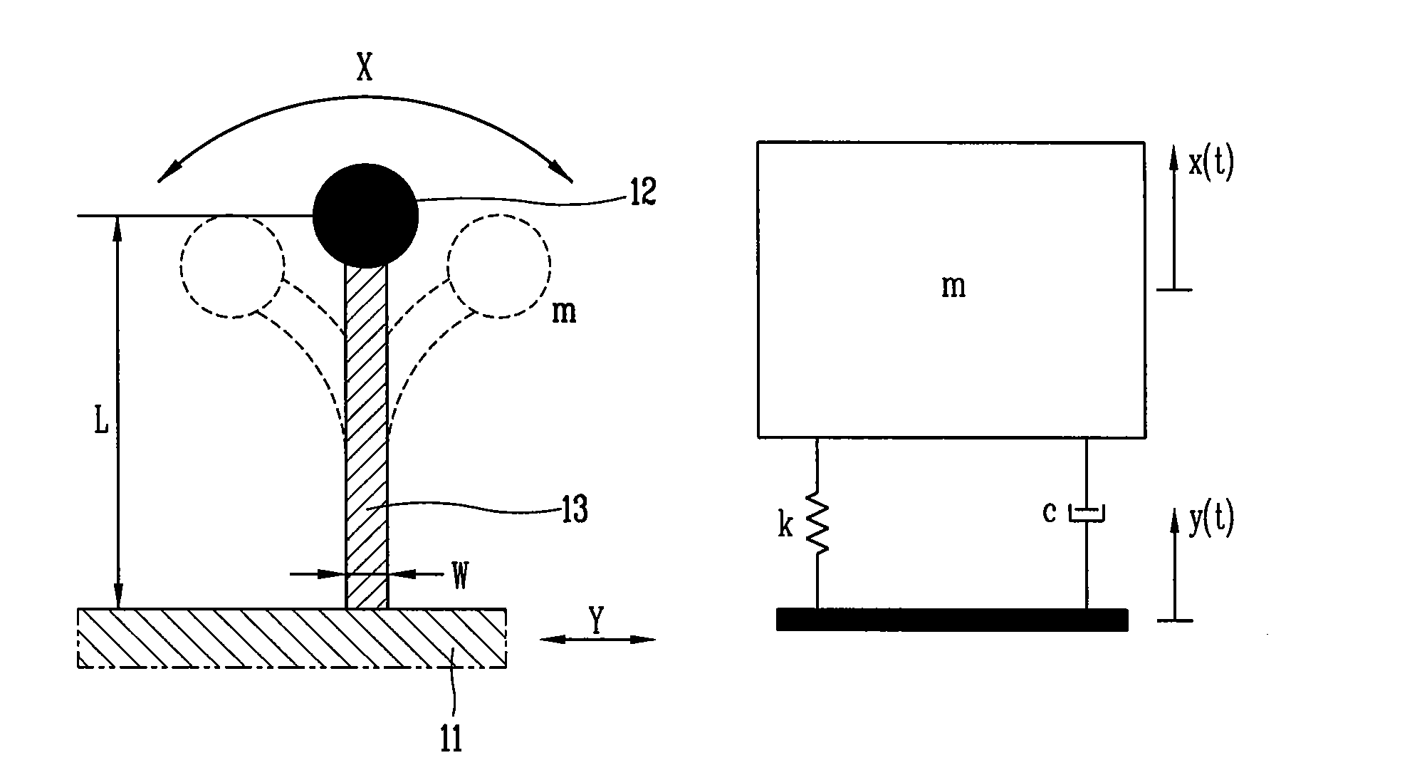
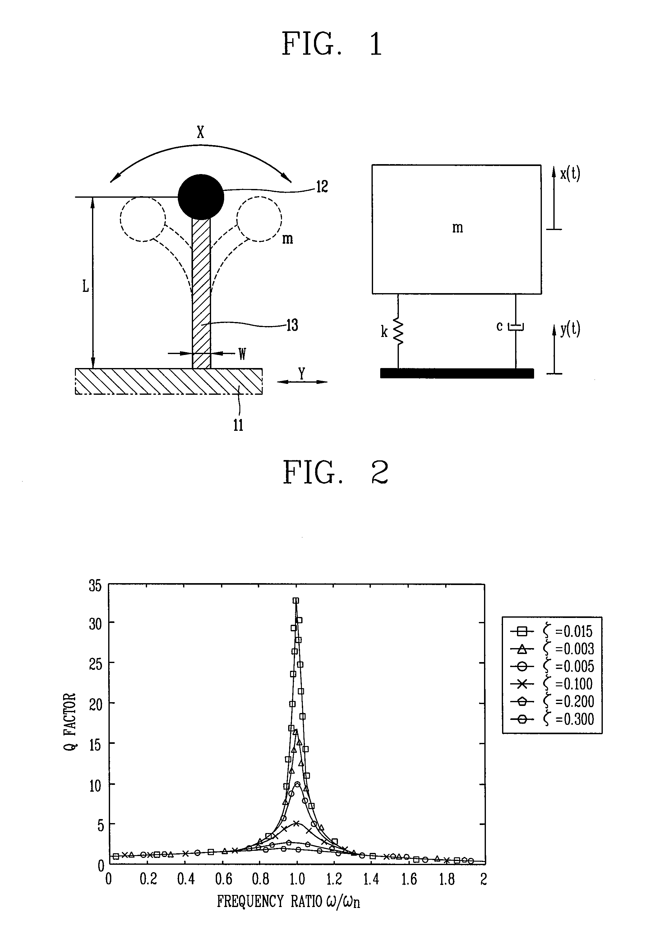
[0040]FIG. 1 is a view illustrating a basic structure of an electric power generating apparatus for a movement type equipment and m-c-k modeling thereof according to the present invention. Herein, L represents a length of a piezoelectric beam, w represents a width, m represents mass, k represents spring constant, c represents damping coefficient, x represents amplitude of a mass part, and y represents amplitude of a base. FIG. 2 is a graph illustrating displacement transmissibility (Q) for the m-c-k modeling of FIG. 1 depending on variation of a frequency ratio (ω / ωn) and a damping ratio (ξ).
[0041]Referring to FIGS. 1 and 2, an electric power generating apparatus according to a first embodiment of the present invention includes a piezoelectric beam 13 and a rectifier unit (not shown). The piezoelectric beam 13 has one end of the piezoelectric beam 13 fixed to a movement type equipment 11 and other end with a mass 12. The rectifier unit rectifies and stores electric energy generated ...
second embodiment
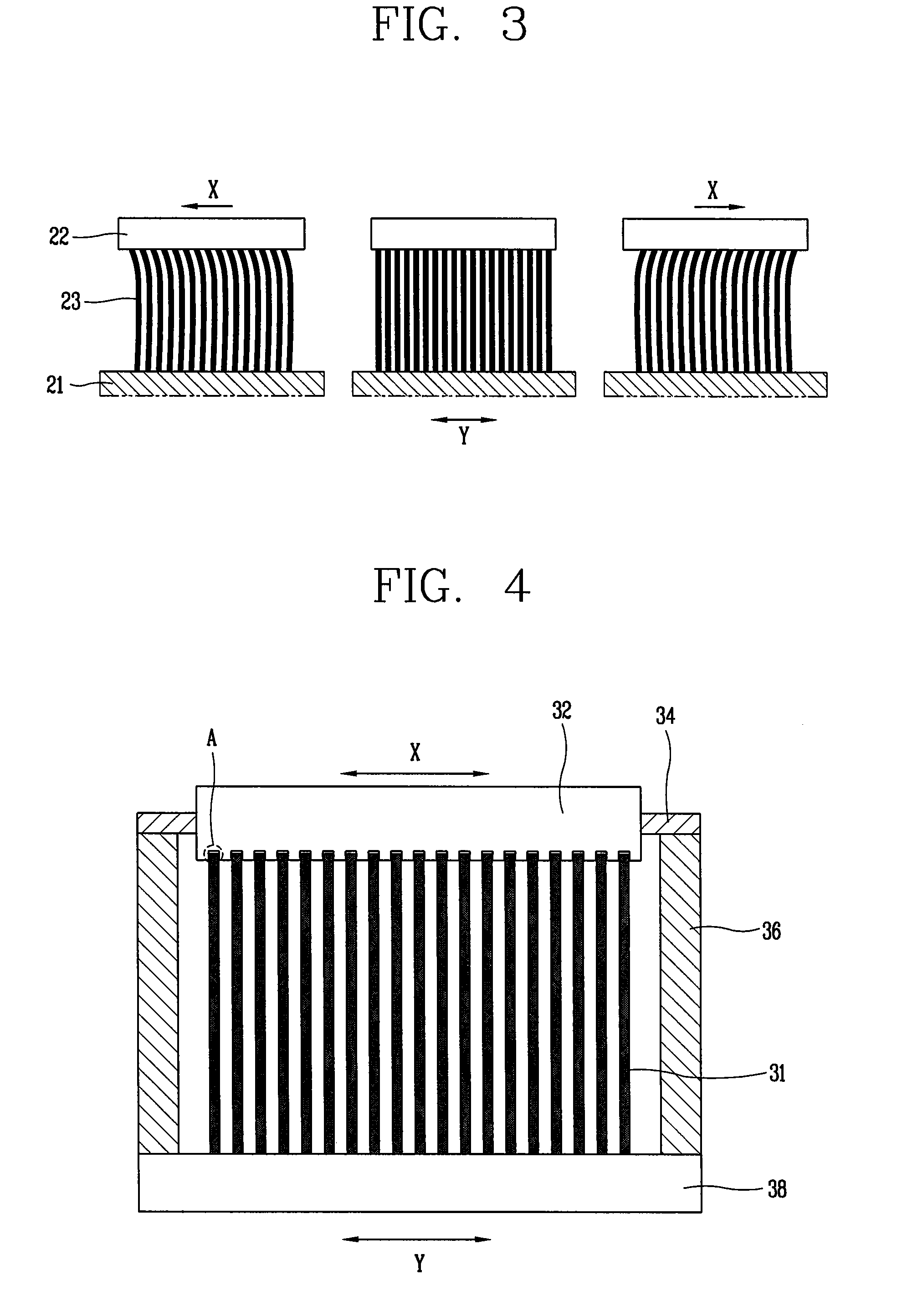
[0046]Referring to FIG. 3, the electric power generating apparatus for the movement type equipment according to the present invention includes a plurality of piezoelectric beams 23 having ends fixed to a movement type equipment 21, a mass part 22 for connecting other ends of the piezoelectric beams 23 with one another, and a rectifier unit (not shown) for rectifying and storing electric energy generated due to deformation of the piezoelectric beams 23.
[0047]Since a single beam has a limit in generating energy, sufficient energy may not be obtained. Therefore, in order to solve such a problem, the electric power generating apparatus for the movement type equipment according to the second embodiment of the present invention includes the plurality of piezoelectric beams 23 disposed in a row on the movement type equipment 21. In this case, since the voltage generated from parallel disposition has displacement of the same phase, the magnitude of generated electric energy increases in pro...
third embodiment
[0049]Referring to FIGS. 4 to 6, the electric power generating apparatus for the movement type equipment according to the present invention includes a base 38, a plurality of piezoelectric beams 31, a mass part 32, a guide unit, a support member 36, a stopper 35, and a rectifier unit 37. The base 38 is mounted on a movement type equipment 30 and the piezoelectric beams 31 are mounted in a row on the base 38. A plurality of mounting grooves 32a are formed in the mass part 32 to connect other ends of the piezoelectric beams 31 to one another, and other ends of the piezoelectric beams 31 are inserted into the mounting grooves 32a. The guide unit guides the mass part 32 so as to slide in an X direction perpendicular to the piezoelectric beams 31. The support member 36 supports the guide unit and the stopper 35 limits the movement range of the mass part 32. The rectifier unit 37 rectifies and stores electric energy generated due to deformation of the piezoelectric beams 31.
[0050]When a m...
PUM
 Abstract
Description
Claims
Application Information
 - R&D
- Intellectual Property
- Life Sciences
- Materials
- Tech Scout
- Unparalleled Data Quality
- Higher Quality Content
- 60% Fewer Hallucinations
Browse by: Latest US Patents, China's latest patents, Technical Efficacy Thesaurus, Application Domain, Technology Topic, Popular Technical Reports.
© 2025 PatSnap. All rights reserved.Legal|Privacy policy|Modern Slavery Act Transparency Statement|Sitemap|About US| Contact US: help@patsnap.com


