High dynamic range optical receiver

a high-dynamic range, optical receiver technology, applied in the direction of transmission, amplifiers, testing/calibration of speed/acceleration/shock measurement devices, etc., can solve the problem of insufficient sensitivity of the circuitry at the lowest light level, inability to provide an output signal proportional to the intensity of light in these situations, and many circuit elements have intrinsic noise that overwhelms very small signals

Active Publication Date: 2008-05-01
AVAGO TECH INT SALES PTE LTD
View PDF4 Cites 6 Cited by
  • Summary
  • Abstract
  • Description
  • Claims
  • Application Information

AI Technical Summary

Problems solved by technology

Providing an output signal that is proportional to the intensity of light in these situations is not practical, since the circuitry that processes the light signals has a fixed maximum potential and sensitivity.
If the circuitry is set to provide the maximum output at the highest intensity, then the sensitivity of the circuitry at the lowest light levels is insufficient.
In this regard, it should be noted that many circuit elements have intrinsic noise that overwhelms very small signals.
If, on the other ha

Method used


Image

  • High dynamic range optical receiver
  • High dynamic range optical receiver
  • High dynamic range optical receiver

Examples


Embodiment Construction

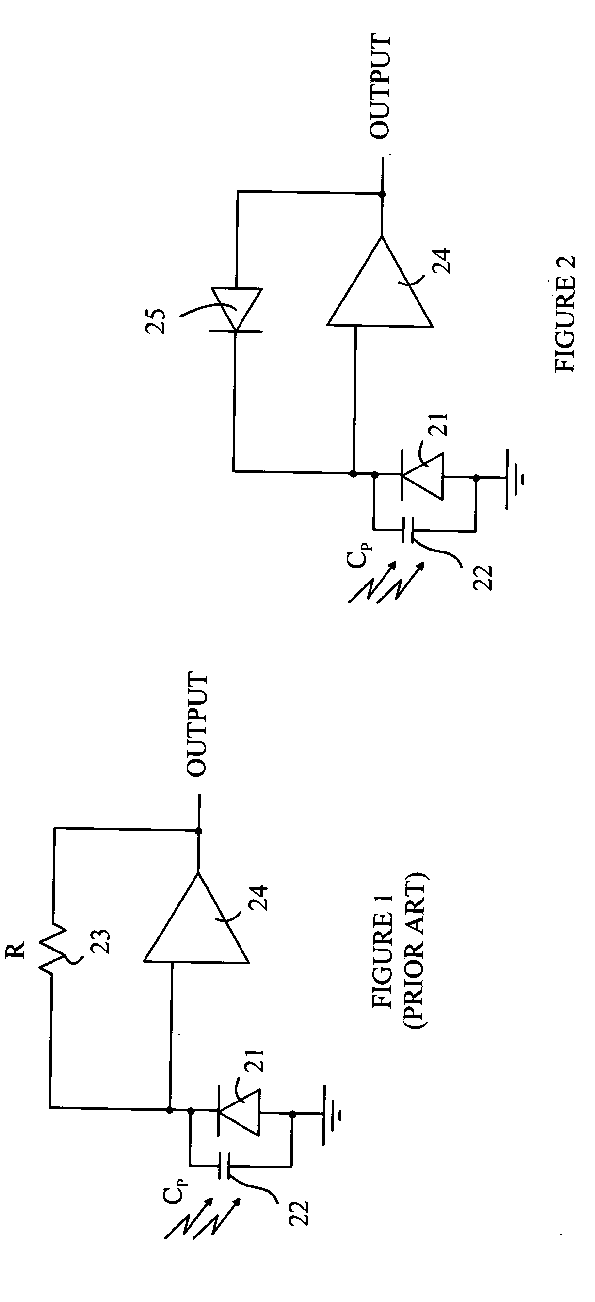
[0012]The manner in which the present invention provides its advantages can be more easily understood with reference to FIG. 1, which is a prior art schematic diagram of a photodiode connected to a conventional TIA. When photodiode 21 is illuminated, a current flows through photodiode 21 and the output of amplifier 24 increases until the same amount of current flows through feedback resistor 23. There is a maximum output voltage that the amplifier can provide. If the feedback resistor is set to provide this output voltage for the highest anticipated value of the photocurrent in photodiode 21, then the sensitivity of the circuit at very low light levels can be insufficient for many applications. Conversely, if the resistance is set at a value that provides high sensitivity at low light levels, the amplifier will saturate at higher levels.

[0013]In principle, this problem can be overcome by replacing resistor 23 with a circuit that changes impedance as the photocurrent changes. The imp...


PUM


Abstract

An optical receiver having a photodetector, amplifier, feedback loop, and output circuit is disclosed. The photodetector generates a current between first and second nodes in response to being illuminated with light. The amplifier has an input connected to the first node and an output connected to a third node. The feedback path connects the third node to the first node, and includes a diode in series with a circuit element having an impedance greater than a predetermined value, the diode is connected between the first and fourth nodes. The output circuit is connected to the fourth node and provides an output signal to an external circuit. The output circuit can be configured to provide an output signal that is proportional to the logarithm of the intensity of the light that illuminates the photodetector.

Description

BACKGROUND OF THE INVENTION[0001]Optical receivers are used in a large number of light sensing applications. The receiver typically includes a photodetector that is illuminated by a light signal and generates a current that is related to the intensity of the light. This current is converted to a voltage by an interface circuit to provide an output signal that is utilized by an apparatus connected to the optical receiver.[0002]In some light sensing applications, an output signal that is proportional to the logarithm of the light intensity is particularly useful. For example, the apparatus that is processing the output signal may need to compute the product or ratio of two light signals. This computation can be performed on the logarithmic signals using simple addition or subtraction circuits.[0003]In other light sensing applications, the amplitude of the light signal can vary by a factor of more than 100,000. Providing an output signal that is proportional to the intensity of light i...

Claims


Application Information

Patent Timeline
IPC IPC(8): H04B10/06
CPCH03F1/08H03F1/34H03F3/082H03G3/3084H03F2200/153H03F2203/45518H03F2203/45528H03F3/087
Inventor RICHARD LUM, KOK KEONGCHEN, LEI
Owner AVAGO TECH INT SALES PTE LTD
Why Eureka
Try Eureka