Interventional catheters incorporating an active aspiration system

a technology of active aspiration and interventional catheter, which is applied in the field of systems and methods, can solve the problems of requiring the use of higher rotational speeds, affecting the health of blood vessel walls, and the relative coarseness of diamond grit, so as to facilitate the further breakdown of materials, facilitate the removal through relatively small diameter lumens, and reduce the viscosity of materials

Active Publication Date: 2008-05-01
BOSTON SCI LTD
View PDF10 Cites 149 Cited by
  • Summary
  • Abstract
  • Description
  • Claims
  • Application Information

AI Technical Summary

Benefits of technology

[0022] The outer surfaces of the projecting bars provided on the masticator central core structure are generally curved and, in some embodiments, generally match the inner surface of a shell structure in which the aspiration port is provided. The projecting bars may have a tapered structure, with a narrower profile toward a proximal end of the masticator assembly and a wider profile toward a distal end of the masticator assembly. The bars may also be configured so that their side walls have different dimensions and different undercut angles along the length of the bars. In general, the side walls are higher and have a smaller undercut angle toward a proximal end of the masticator assembly and are lower and have a larger undercut angle toward a distal end of the masticator assembly. As particulate material is drawn into the aspiration port by aspiration forces, the rotating macerator assembly facilitates further breakdown of the material and assists in moving the particulate material proximally and through the aspiration conduit for downstream collection and disposal.
[0023] L

Problems solved by technology

Relatively coarse diamond grit is more likely to damage elastic, healthy tissue such as blood vessel walls.
Relatively fine diamond grit has slow material removal rates, requiring the use of higher rotational speeds.
Despite the many and varied approaches to material removal from lumens such as blood

Method used


Image

  • Interventional catheters incorporating an active aspiration system
  • Interventional catheters incorporating an active aspiration system
  • Interventional catheters incorporating an active aspiration system

Examples


Embodiment Construction

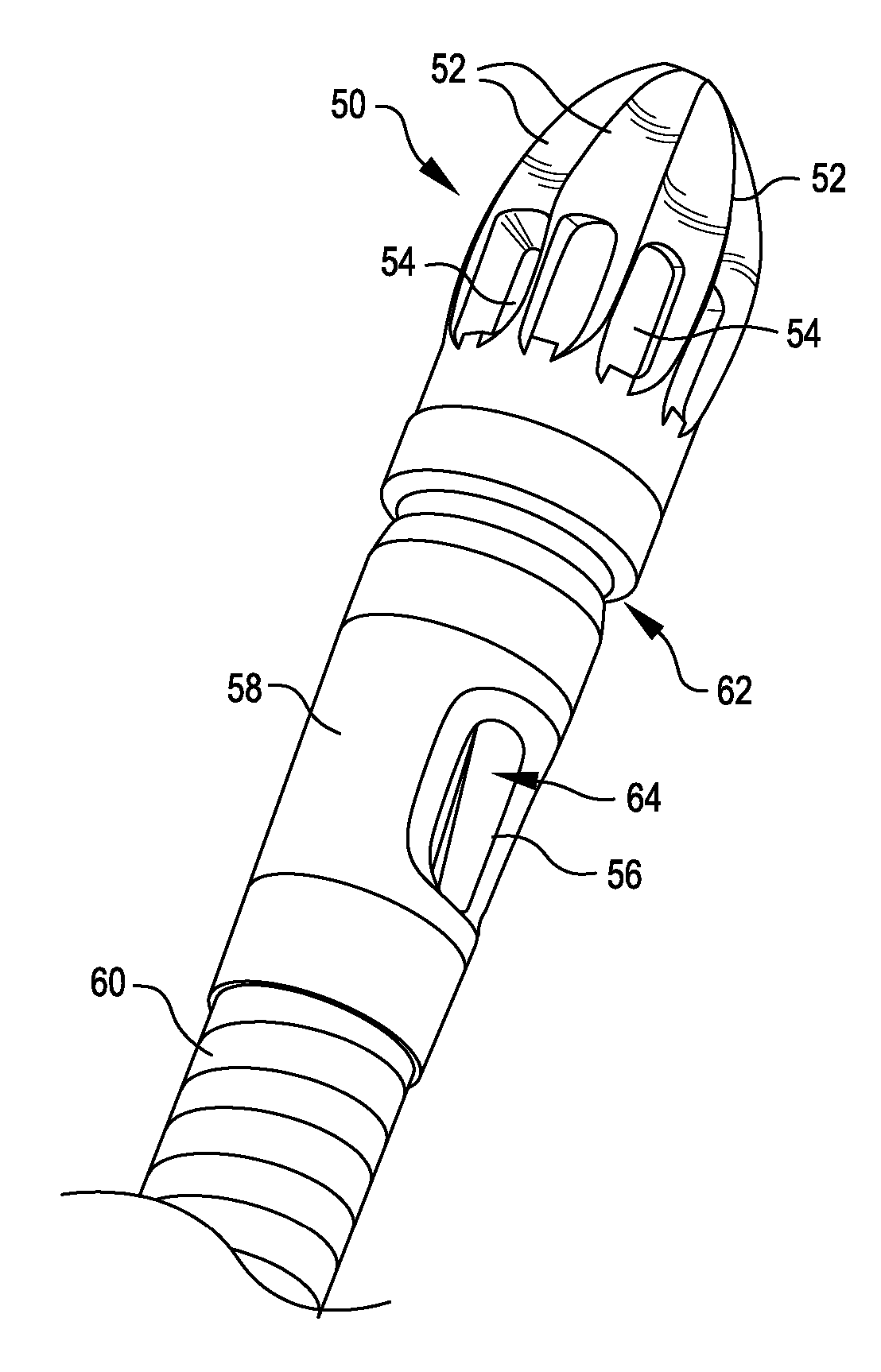
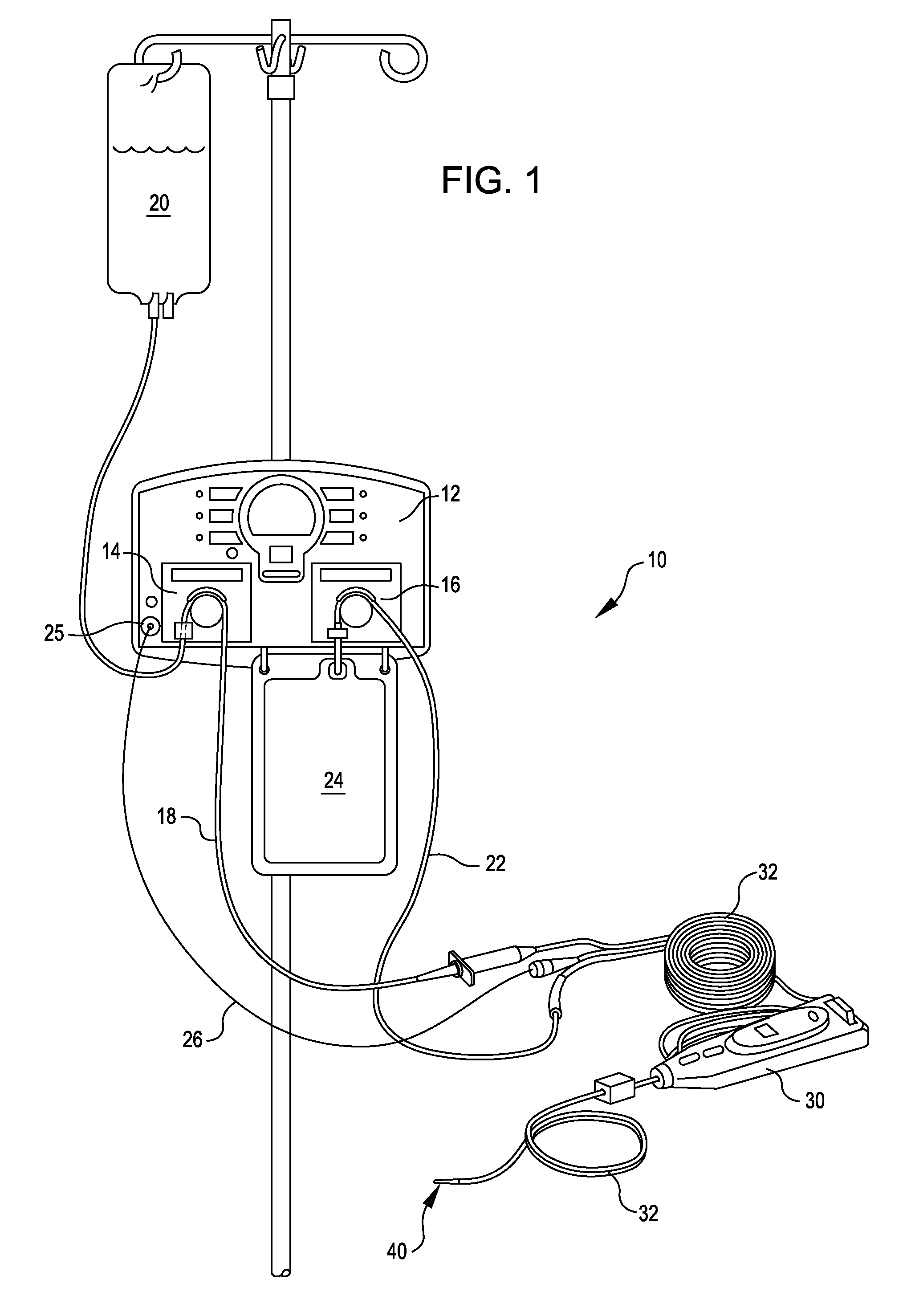
[0033] Certain preferred embodiments are described herein with reference to a material removal device having a rotational cutting head. It will be appreciated that this device embodiment is being described as illustrative and that the inventions and features disclosed herein are applicable to interventional catheters having different types of operating heads.

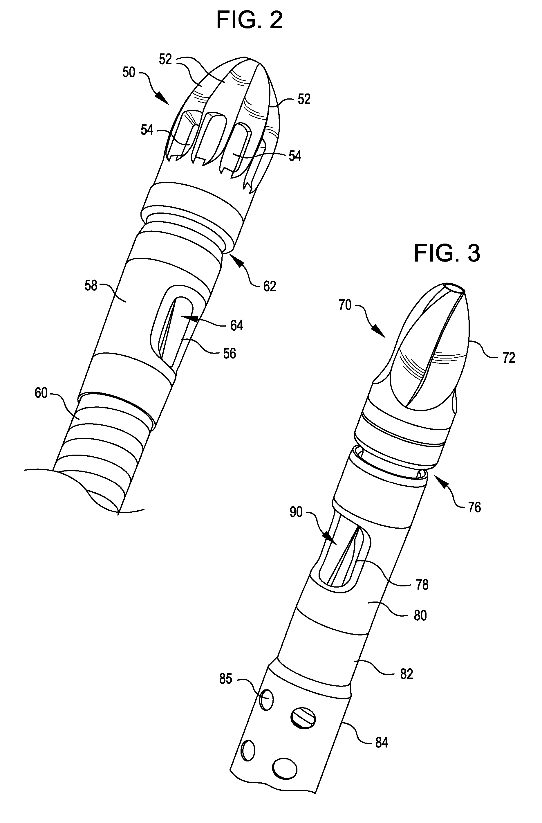
[0034]FIG. 1 illustrates an exemplary embodiment of an interventional catheter assembly, including a console unit incorporating aspiration and infusion systems as disclosed herein. Interventional catheter assembly 10 comprises console unit 12, controller 30, and catheter system 32 having an operating head 40 located at or in proximity to the distal end of the catheter system. Controller 30 may be used to manipulate (e.g. advance and / or rotate) the catheter system 32 and operating head 40, or alternative controls may be provided.

[0035] Console unit 12 incorporates an infusion pump 14 and an aspiration pump 16. During operation ...


PUM


Abstract

An interventional catheter assembly comprises an operating head for removing obstructive material from a target site in a body lumen or cavity and at least one aspiration port located proximal to the operating head and penetrating the catheter assembly, the aspiration port being in communication with a sealed lumen that communicates with a vacuum system for withdrawing aspirate fluid and obstructive material from the target site. A rotatable member is positioned inside the catheter assembly at the site of the aspiration port and rotates during operation of the vacuum system. The rotatable member is provided with at least one upstanding bar that is sized to cooperate with the walls of the aspiration port and the inner surface of the catheter assembly to macerate debris that is drawn into the aspiration port.

Description

REFERENCE TO PRIORITY APPLICATIONS [0001] This application claims priority to U.S. Provisional Patent Applications No. 60 / 894,173 filed Mar. 9, 2007, and 60 / 828,209 filed Oct. 4, 2006. The disclosures of these priority applications are incorporated by reference herein in their entireties.FIELD OF THE INVENTION [0002] The present invention relates to systems and methods for removing material, such as obstructions and partial obstructions, from an internal lumen or cavity of a mammalian subject, such as a blood vessel. More particularly, the present invention relates to interventional catheters having an operating head incorporating a device for removing obstructions and partial obstructions from a lumen or cavity, and an active aspiration system for removal of fluids and debris cleared from the target site. BACKGROUND OF THE INVENTION [0003] Removal of disease such as atherosclerotic plaque, thrombus and other types of obstructions and partial obstructions from internal body lumens o...

Claims


Application Information

Patent Timeline
IPC IPC(8): A61M31/00
CPCA61B17/3207A61B17/320758A61B2017/320775A61B2217/005A61B2217/007A61M25/09A61B1/05A61B8/12A61B8/445A61M1/0084A61B1/00087A61M1/84A61M1/71A61M1/80A61B17/22A61B17/32A61M25/00A61B2017/22079A61M5/142A61M5/16831A61M25/0082A61B17/32002A61B17/320725A61B2017/320004A61B2017/320032
Inventor TORRANCE, CASEYAUTH, DAVID
Owner BOSTON SCI LTD
Why Eureka
Try Eureka