
Method for Testing Separation Modules

a technology of separation module and test method, applied in the direction of porous material analysis, suspension, membrane, etc., to achieve the effect of enhancing permeation signal, improving sensitivity to defects, and enhancing signal

Inactive Publication Date: 2008-05-08
DOW GLOBAL TECH LLC
View PDF20 Cites 40 Cited by
  • Summary
  • Abstract
  • Description
  • Claims
  • Application Information

AI Technical Summary

Benefits of technology

[0019]We have discovered that improved sensitivity to defects results from testing of spiral wound modules by introducing to the feed stream of a module a short pulse of a challenge species that is well-rejected by the membrane and measuring the time-dependent concentration of challenge species that results within the permeate stream. The resulting time-dependent permeate signal may be detected, recorded, and compared to a reference. As compared to conventional integrity tests performed when the permeate concentration is in quasi-steady-state, this time dependence of permeate signal can provide improved differentiation, allowing leaks to be more readily discovered. The method is applicable to feed pulses of challenge species added over a period as long as four minutes but more preferably uses substantially shorter pulse durations of less than or equal to two minutes or even more preferably less than or equal to 40 seconds or less than or equal to 5 seconds, to obtain permeate responses characteristic of “intact” and leaking filtration systems. Using a non-steady-state permeate concentration enhances permeate signal against a variable background due to the short measurement time interval and it also enhances signal because the response from defects can be concentrated in a short time compared to passage of challenge species through “good” membrane. In addition, a non-steady state allows high concentrations of challenge species to be used in the pulse, even in cases where the osmotic pressure approaches or exceeds the applied pressure. In a preferred embodiment the challenge pulse may temporarily increase osmotic strength to dramatically reduce the system's net driving potential and enhance the magnitude of signal from leaking regions. The method of this invention has an additional advantage of allowing collection and re-use of a substantial fraction of the rejected challenge species.
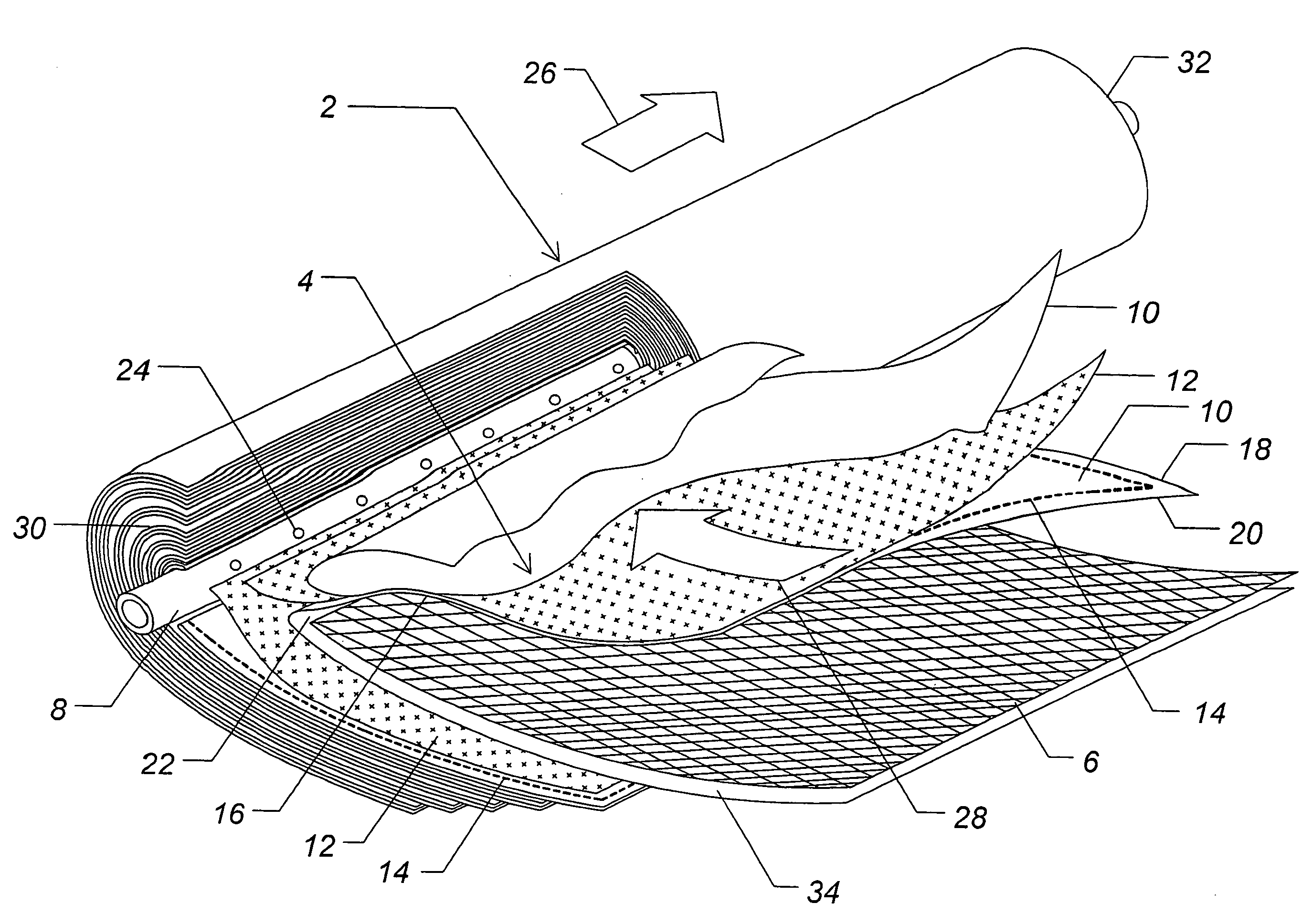
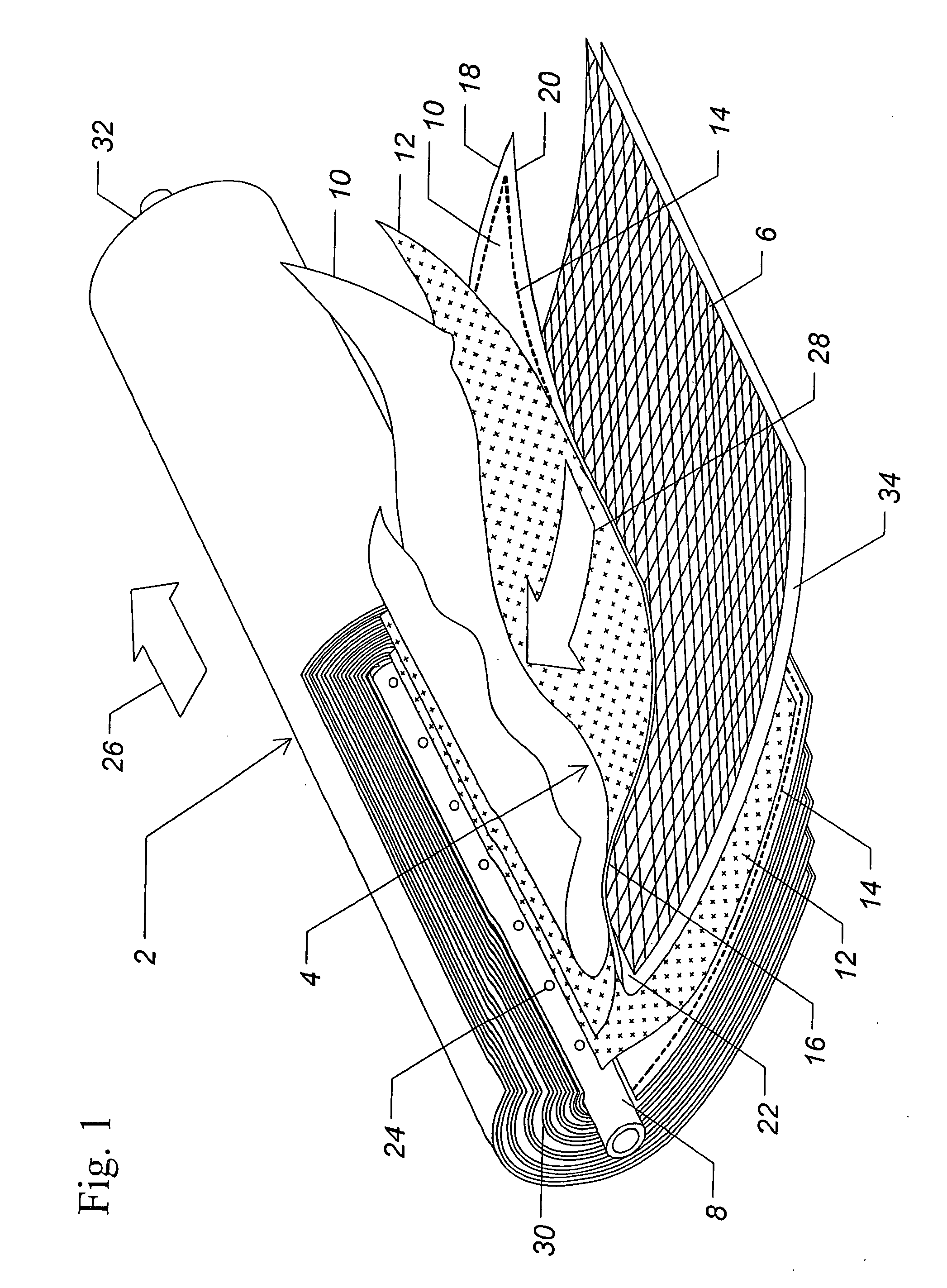
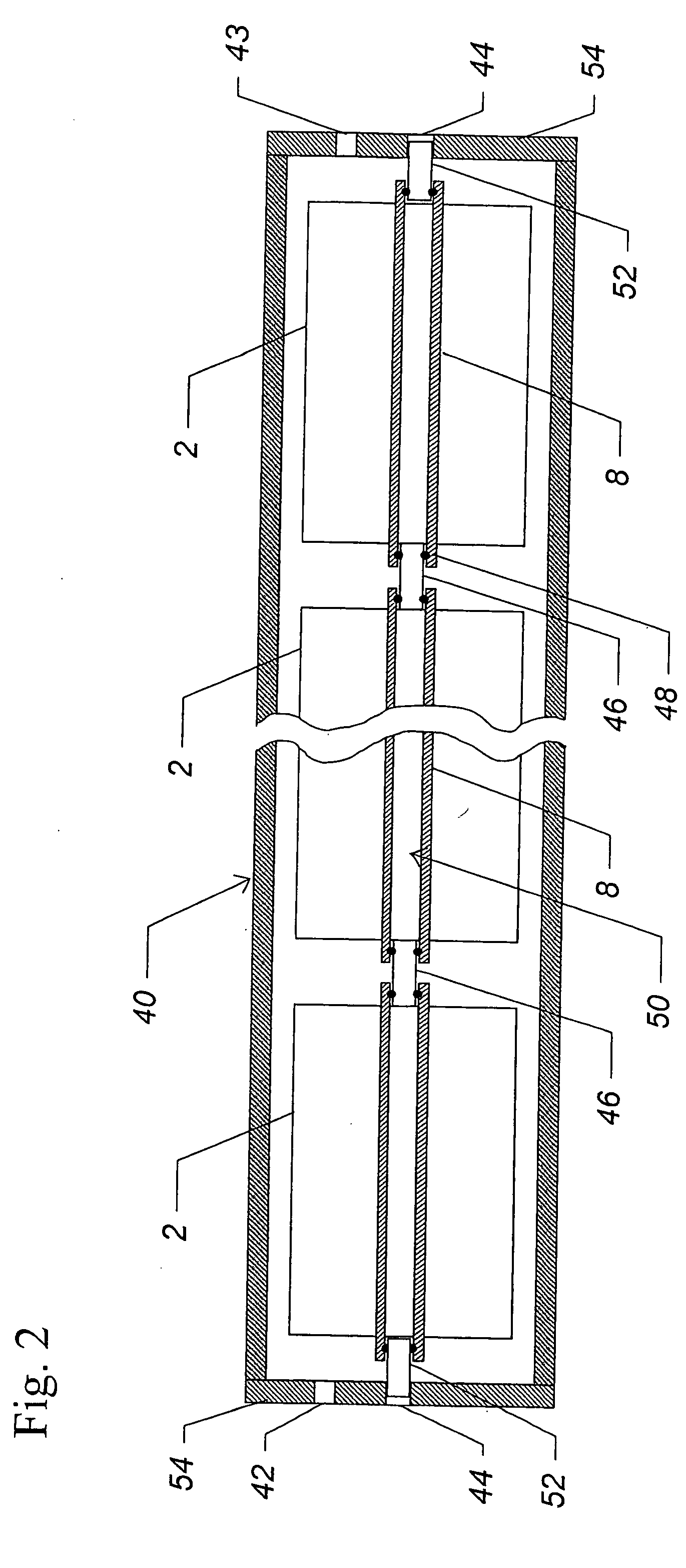
[0020]We have further found that measuring the concentration of challenge species at several positions along the permeate tube within the module provides improved sensitivity to defects. The concentration at each measurement point along the permeate tube varies as a function of time, as the feed with concentrated challenge species traverses the length of the module and as permeate moves down the permeate carrier sheet. Another embodiment of this invention includes a means to measure conductivity from at least four points within a vessel's permeate collection region. Particularly in combination with a short pulse of challenge species, the claimed device can provide substantially improved sensitivity to defects, and may allow both the location, and in some cases even cause, of defects to be ascertained in a non-destructive test. When used with either a single module or multiple modules within a vessel, the probe device is preferably adapted to detect leaks from interconnector seals upstream of one module. When used with multiple modules inside a vessel, the probe is most advantageously combined with interconnectors that avoid constricting the inner diameter of the vessel's permeate collection region.
[0021]Another embodiment of this invention includes a device for sampling the permeate stream of a filtration system, concentrating a challenge species within that stream using a high recovery membrane apparatus, and then detecting the challenge species within the high recovery membrane apparatus' reject solution that would otherwise be more difficult to measure. Since the claimed device provides a means for continuous concentration and detection of challenge species, it can be very advantageously combined with the pulse test to improve sensitivity. The device's high recovery membrane apparatus preferably includes a feed spacer having substantially decreased cross sectional area at its outlet end.

Problems solved by technology

In addition, a non-steady state allows high concentrations of challenge species to be used in the pulse, even in cases where the osmotic pressure approaches or exceeds the applied pressure.

Method used


Image

  • Method for Testing Separation Modules
  • Method for Testing Separation Modules
  • Method for Testing Separation Modules

Examples


example 1

[0064]A spiral wound brackish water hyperfiltration module was run at 67 psi using a pure water feed. For thirty seconds, the feed to the module was switched to a solution of 2000 ppm MgSO4. The feed source was switched back to pure water, and the resulting pulse in feed challenge concentration, as determined by conductivity measured at the input end of the module, had a FWHM of less than 40 seconds. The relative challenge concentrations within the feed pulse is shown as #0 in FIG. 6.

[0065]Within the permeate tube of the spiral wound module, a probe segregated permeate from selected regions corresponding to individual holes in the permeate tube. The probe comprised twelve conduits (0.0125″ outer diameter) of more than one meter in length. The presence of these many conduits within the permeate tube would have substantially increased backpressure on the module, although this increase was not measured.

[0066]FIG. 6 shows the relative concentrations measured by conductivity sampled from...

example 2

[0068]A spiral wound seawater hyperfiltration module (FilmTec SW30-2540) having an insert leak at one end was tested using the method of the invention using a pulse of challenge species in the feed. The pulse was created by temporarily replacing pure water with a challenge species feed solution of 1700 ppm MgSO4. The FWHM of the pulse was slightly less than 40 seconds. The applied pressure during the test was 227 psi.

[0069]The 40 inch long module was tested with two different orientations. In a first test, the module was oriented relative to the pressure vessel so that the insert leak was at the inlet end. All permeate was removed from that inlet end of the module. In a second test, the module was reversed so that the leak was at the end farthest away from both the inlet end and the permeate removal end. The second test demonstrated a delay of ten seconds in the peak position relative to the peak position observed in the first test. We believe this delay was due to this change in or...

example 3

[0070]Twenty seawater spiral wound modules (FILMTEC SW30-2540) were tested using the method of the invention at 150 psi applied pressure with a challenge pulse. Pure water was replaced temporarily with a pulse having FWHM less than 40 seconds. At its peak concentration, this feed pulse was approximately 3% MgSO4, resulting in an osmotic strength of about 100 psi. Conductivity was used to measure concentration of the permeate and was recorded as a function of time during this pulse test.

[0071]“Intact” modules, as determined from later standard seawater tests (3.2% NaCl, 800 psi), demonstrated similar time profiles for MgSO4 in the permeate. FIG. 7 shows a time profile for a leaking module (A) and for an “intact” module (B). The leaking module demonstrated higher peak concentration and an earlier peak elution time, both individually indicative of a defect. In this example, improved sensitivity to defects can also be obtained by subtracting the time profile for a typical “intact” modul...


PUM


Abstract

New methods and apparatus are described for assessing the integrity of a separation module or filtration system. A principle embodiment concerns use of a transient pulse of challenge species to probe a spiral wound module. The resulting time-dependent concentration of challenge species in the permeate is detected, recorded, and compared to a reference. An apparatus is further claimed for detecting permeate conductivity at multiple points within the permeate collection tube of a spiral wound module. Also disclosed is a process whereby the permeate stream from a filtration system is concentration by a high recovery membrane apparatus prior to measurement of challenge species concentration.

Description

FIELD OF THE INVENTION[0001]The present invention pertains to a method and a device for evaluating the integrity of a separation module or filtration system. The method of this invention is particularly useful for spiral wound hyperfiltration modules and systems comprising these modules. Rapid test methods of the invention improve capability to detect leaks, and are useful for quality testing by module manufacturers. One embodiment also allows leaks in an installed system to be located with no interruption of service. A preferred embodiment determines the location of leaks within a module or within a filtration system, using a non-destructive test.BACKGROUND[0002]Hyperfiltration is a process whereby pressure is applied to one side of a semi-permeable membrane, causing a solvent (commonly water) to pass through the membrane while a solute (often a salt) is retained. To overcome the natural drive for solvent to move from low concentration to high concentration, the applied pressure mu...

Claims


Application Information

Patent Timeline
IPC IPC(8): G01N15/08
CPCB01D61/027B01D65/104B01D63/12B01D2311/06B01D2311/243
Inventor JONS, STEVEN DOUGLASJOHNSON, JON E.FIALKOWSKI, MICHAEL A.
Owner DOW GLOBAL TECH LLC
Learn More