
Ultrafine alloy particles, and process for producing the same

a technology alloy powders, applied in the field of ultrafine alloy particles, can solve the problems of not meeting the demands of ultrafine powder, the limit of raising the heating temperature applied to and the inability of ultrafine powder to form wirings on semiconductor substrates or printed wiring boards

Active Publication Date: 2008-05-08
NISSHIN ENG +1
View PDF6 Cites 79 Cited by
  • Summary
  • Abstract
  • Description
  • Claims
  • Application Information

AI Technical Summary

Benefits of technology

The present invention provides a method for producing ultrafine alloy particles that have no adhesiveness and are highly resistant to oxidation. These particles have a particle size of a few nanometers and are coated with a thin film of carbon atoms. The invention solves the problem of ultrafine powder not being able to be heated to high temperatures for wiring on semiconductor substrates or printed wiring boards. The ultrafine alloy particles have a high surface activity and novel functionality, and can be used in various applications such as semiconductor devices and printed wiring boards. The invention also provides a process for producing these particles using a thermal plasma flame.

Problems solved by technology

For this purpose, the ultrafine powder needs to be heated to a high temperature, but there is a limit in raising a heating temperature applied to semiconductor substrates or printed wiring boards.
Therefore, a problem lies in the fact that the ultrafine powder cannot be used to form wirings on semiconductor substrates or printed wiring boards.
More particularly, the “ultrafine powder whose particles are coated with a carbon ultrathin film” described in JP 05-043791 B had a problem that the ultrafine powder does not satisfy the demands for wirings as described above which require particle surfaces to be substantially metallic (to thus impart conductivity also to the particle surfaces).

Method used


Image

  • Ultrafine alloy particles, and process for producing the same
  • Ultrafine alloy particles, and process for producing the same
  • Ultrafine alloy particles, and process for producing the same

Examples


example 1

[0130] First, an example in which ultrafine alloy particles comprising an alloy of silver and palladium were produced and agglomeration and coalescence of the particles to each other were prevented is presented.

[0131] As raw materials of a material for producing the ultrafine alloy particles, a silver powder having an average particle size of 4.5 μm and a palladium powder having an average particle size of 5 μm were used. The mixture mass ratio (mixing ratio) between the silver and palladium was 87:13.

[0132] As to melting points of silver and palladium, it is known that palladium has a melting point of 1540° C., which is higher than that of silver. At the temperature of the melting point of palladium, 1540° C., a vapor pressure of silver reaches 7.14×10⁻² Pa while that of palladium is 6.28×10⁻⁵ Pa, resulting in a vapor pressure ratio of 1:8.80×10⁻⁴ (0.880×10⁻³) (i.e., 1137:1) on the order of 10−3 difference.

[0133] Here, argon was used as a carrier gas.

[0134] The high frequency o...

example 2

[0139] Next, an example is shown in which the ultrafine alloy particles comprising an alloy of iron and aluminum were produced, and agglomeration and coalescence of the particles to each other were prevented.

[0140] As raw materials, an iron powder having an average particle size of 3 to 5 μm and an aluminum powder having an average particle size of 5 μm were used. The mixture mass ratio (mixing ratio) between the iron and aluminum was 98:2.

[0141] As to melting points of iron and aluminum, it is known that iron has a melting point of 1550° C., which is higher than that of aluminum. At the temperature of the melting point of iron, 1550° C., a vapor pressure of iron reaches 2.67×10⁻⁴ Pa while that of aluminum is 1.37×10⁻⁶ Pa, resulting in a vapor pressure ratio of 1:5.13×10⁻³ (i.e., 195:1) on the order of 10−2.3 difference.

[0142] Similarly to Example 1, argon was used as a carrier gas.

[0143] Here, the high frequency voltage to be applied to the plasma torch 12 and the supply amount...

examples 3-12

[0159] Ultrafine alloy particles comprising a primary metal and a subsidiary metal were produced in Examples 3 to 12 using raw material powders in the respective combinations of the primary metal and the subsidiary metal shown in Table 1 under the same production conditions and through same processes as those in Example 1. Raw material powders of the primary metal and the subsidiary metal having average particle sizes, vapor pressure ratios (primary metal / subsidiary metal) and mixture mass ratios therebetween as shown in Table 1 were used in Examples 3 to 12.

[0160] Each particle size of the ultrafine alloy particles produced in Examples 3 to 12 was obtained similarly to Example 1.

[0161] The results are shown in Table 1.

TABLE 1MixtureAverage Particle Size of Raw Material PowdersMass RatioAverageAverage(PrimaryParticleSub-ParticleMetal:VaporUltrafineParticlePrimarySizesidiarySizeSubsidiaryPressureAlloySizeMetal(μm)Metal(μm)Metal)RatioParticles(nm)Ex. 3Ag4.5Cu585:1562.5:1Ag—Cu30Ex....


PUM

PropertyMeasurementUnit
thicknessaaaaaaaaaa
core particle sizeaaaaaaaaaa
sizeaaaaaaaaaa

Abstract

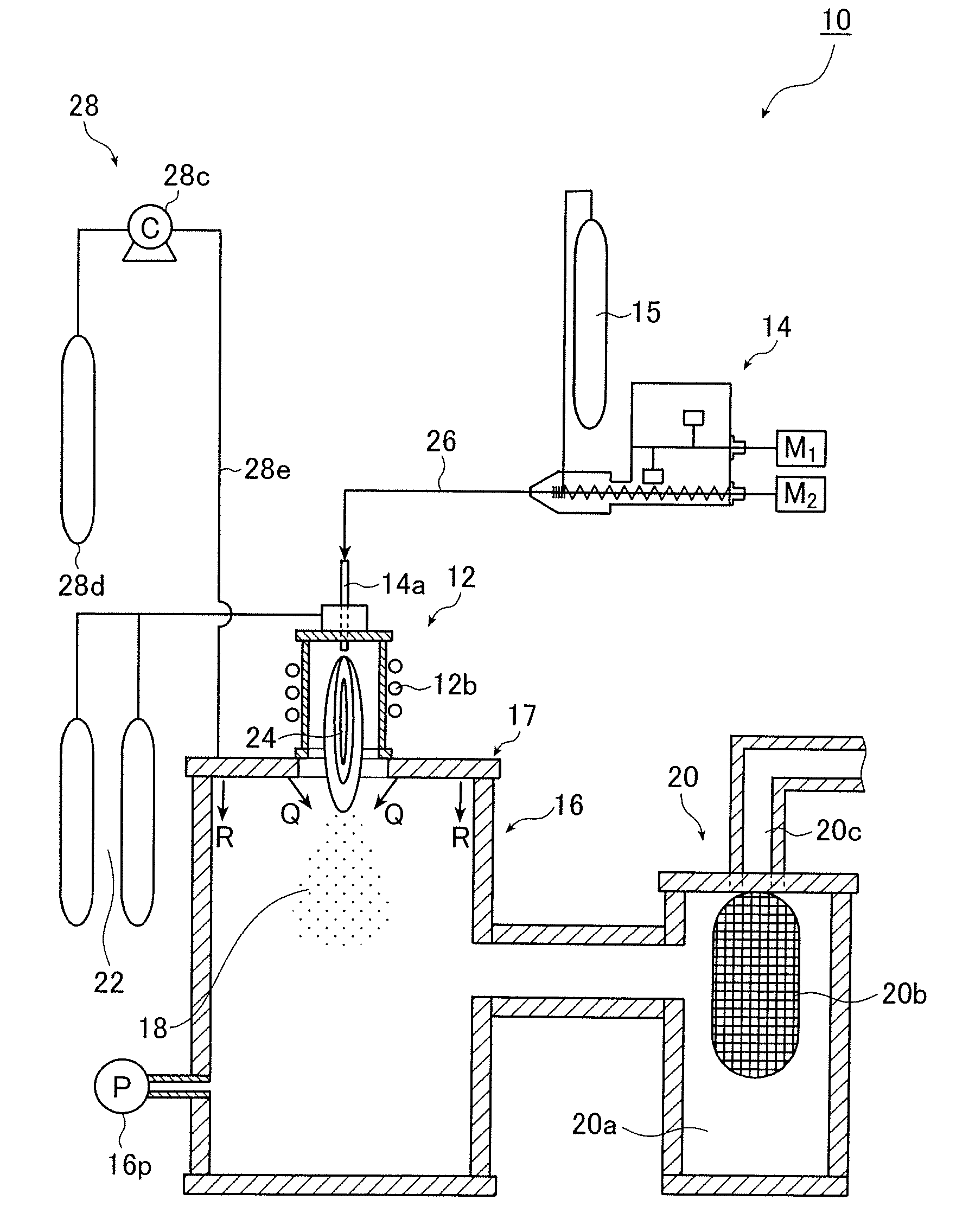
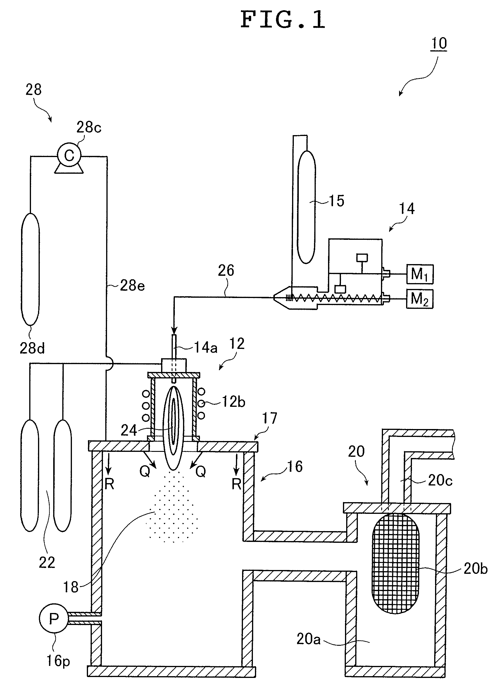
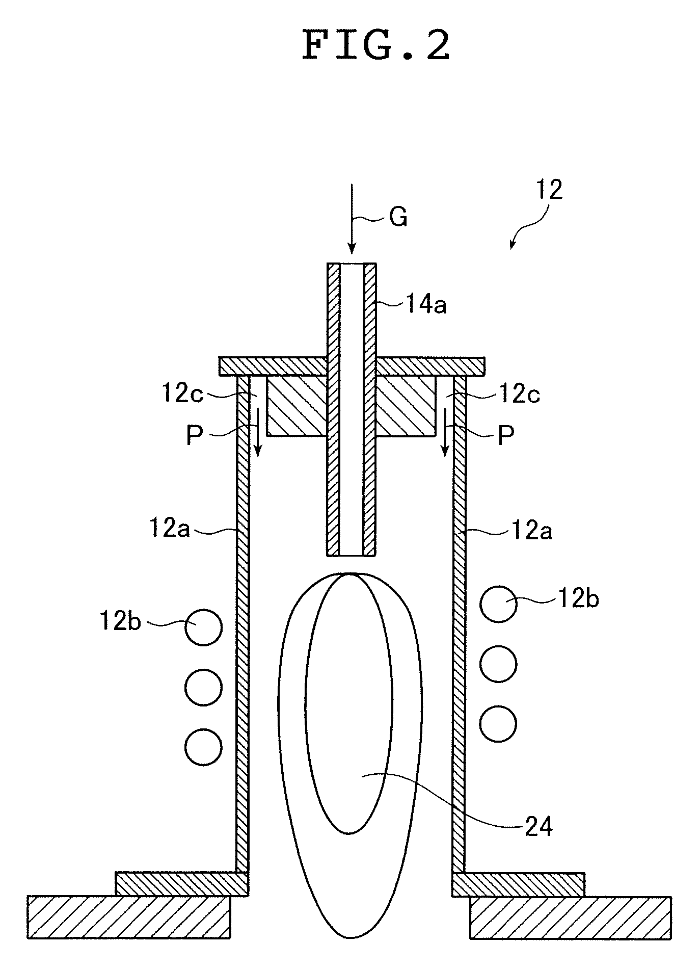
The Ultrafine alloy particles of an alloy includes a primary metal and one or more subsidiary metals solid-soluble in said primary metal, a content of the one or more subsidiary metals is in a range of 1 wt % to 25 wt % and the one or more subsidiary metals solid-solved in the primary metal inhibit coalescence or oxidation of the ultrafine alloy particles including the primary metal, or both. The process introduces powder materials including the primary metal and the one or more subsidiary metals for producing the ultrafine alloy particles into a thermal plasma flame under reduced pressure to form a vapor-phase mixture and introduces a cooling gas toward an end portion of the thermal plasma flame in a supply amount sufficient for quenching the vapor-phase mixture so as to generate the ultrafine alloy particles.

Description

[0001] The entire contents of the documents cited in this specification are herein incorporated by reference. BACKGROUND OF THE INVENTION [0002] The present invention relates to ultrafine alloy particles capable of preventing coalescence and inhibiting oxidation and a process for producing the same. More particularly, the present invention relates to ultrafine alloy particles including a primary metal and one or more subsidiary metals solid-soluble in the primary metal obtained by a thermal plasma method, and a process for producing such the ultrafine alloy particles. The primary metal and the one or more subsidiary metals can be specifically exemplified as a primary metal A and one or more metals selected from a plurality of metals B, C and so forth solid-soluble in the primary metal A. [0003] Fine particles such as oxide fine particles, nitride fine particles, and carbide fine particles have been used in the production of sintered bodies, for example, electrical insulating materia...

Claims


Application Information

Patent Timeline
Patent Type & Authority Applications(United States)
IPC IPC(8): B22F9/00B22F1/00B22F1/054
CPCB22F1/0018B22F9/12B22F2999/00B82Y30/00B22F2202/13B22F1/054B22F1/00B22F9/08
Inventor NAKAMURA, KEITAROHFUJII, TAKASHI
Owner NISSHIN ENG
Learn More