Physisorption-based microcontact printing process capable of controlling film thickness

a micro-contact printing and printing technology, applied in the field of physical sorption-based micro-contact printing technology, can solve the problems of ineffective control of the amount of ink molecules applied, let alone the thickness control of the printed pattern, and achieve the effects of reducing surface roughness and residual internal stress, improving surface smoothness, and improving surface smoothness

Inactive Publication Date: 2008-05-15
NATIONAL CHUNG CHENG UNIV
View PDF21 Cites 11 Cited by
  • Summary
  • Abstract
  • Description
  • Claims
  • Application Information

AI Technical Summary

Benefits of technology

[0024]The primary objective of the present invention is to provide a physisorption-based microcontact printing process capable of controlling film thickness primarily for creating patterns of organic thin films in micron and submicron scales, which effectively controls the thickness of the printed organic patterns.
[0025]The secondary objective of the present invention is to provide a physisorption-based microcontact printing process capable of controlling film thickness primarily for creating patterns of organic thin films in micron and submicron scales, which controls the quality of surface roughness and residual internal stress in the printed organic patterns.
[0028]On the one hand, the μCP is to print the ink molecules on the stamp onto the substrate, so the stamp is made of a material with very low surface free energy to reduce the affinity between the ink molecules and stamp, thus facilitating the transfer printing of the ink molecules. On the other hand, an effective thin-film growth requires high affinity between the molecules of the thin-film and the surface of the substrate to enable deposition of a high-quality homogeneous thin film with a smooth surface. The first step of the inking phase of the present invention, i.e. surface wetting, is to reconcile the conflict between the requirement of a successful transfer printing and that of a high-quality thin-film growth. Thus, to succeed in the surface wetting, it requires two conditions as follows: effective enhancement of the affinity between the stamp surface and the ink molecules and such enhancement must be impermanent. There are two feasible methods of the surface wetting as follows. First, the stamp is coated with a wetting layer made of highly evaporative solvent properly selected to effectively enhance the affinity between the stamp surface and the ink molecules and such enhancement is impermanent because of the high evaporation rate of the solvent. Second, the stamp is done with some special surface treatment. One possible treatment is the O2 plasma treatment. According to DGB01, the PDMS stamp with low surface free energy can be treated by O2 plasma to generate a wetting layer composed of hydroxyl, carboxyl, or peroxide to enhance the surface free energy of the PDMS stamp and such enhancement of the surface free energy holds for about one day only.
[0031]In the printing phase, similar to that of the thermal assist μCP, the substrate and the stamp are not only heated to enhance the temperature thereof but also applied with an adequate pressure. The enhancement of the temperature of the substrate and the stamp improves not only the wetting condition between the ink molecules and the substrate but the adhesive condition therebetween; the applied pressure increases the effective contact area between the thin film of ink molecules and the substrate to improve the adhesion to each other; and both together successfully transfer the ink molecules to the substrate.
[0033]The currently available μCP technology did not particularly elaborate on the demolding phase but merely mentioned that the stamp is removed to complete the whole μCP after a given time of printing contact. For better surface smoothness and reduced residual internal stress in the transferred pattern, the present invention proposes an additional demolding phase where the removal of the stamp is a precisely controlled process rather than a simple removal. In the demolding phase, as the temperature of the transferred ink molecules decreases, the pressure applied to them is also lowered according to the P-V-T rheological data of the ink molecules in order to give rise to a transferred pattern with reduced surface roughness and residual internal stress.

Problems solved by technology

These methods do not offer effective control in the amount of ink molecules applied, let alone the thickness control of the printed pattern.

Method used


Image

  • Physisorption-based microcontact printing process capable of controlling film thickness
  • Physisorption-based microcontact printing process capable of controlling film thickness
  • Physisorption-based microcontact printing process capable of controlling film thickness

Examples


Embodiment Construction

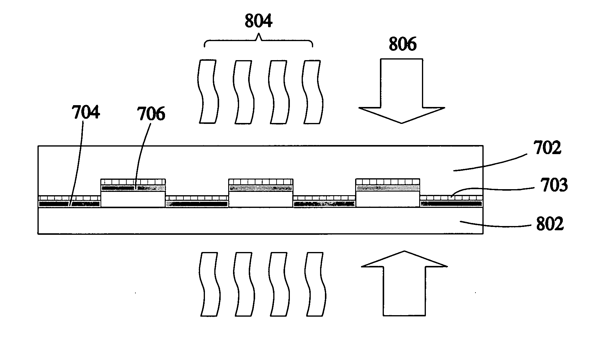
[0044]The present invention proposes a physisorption-based microcontact printing process capable of controlling film thickness, including three phases of inking, printing, and demolding. The inking phase further has two steps of surface wetting and thin-film growth. The surface wetting step is optional, depending on whether it is necessary. When it is necessary, a wetting layer is deposited onto a stamp to facilitate successful growth of a thin film of the ink molecules on the stamp in the next thin-film growth step. In the following preferred embodiments, the surface-wetting step is required.

[0045]FIG. 7a shows a pre-patterned stamp 702 made of a material having very low surface free energy, such as PDMS. Referring to FIG. 7b, a wetting layer 703 is formed on a surface of the stamp 702 after surface wetting. The wetting layer 703 can be made of highly evaporative solvent, like toluene, or of highly reactive function group generated after surface treatment of the stamp 702. For exam...


PUM


Abstract

The disclosed is a physisorption-based microcontact printing process capable of controlling film thickness, primarily for creating patterns of thin film of organic molecules in micron and submicron scales, comprising an inking phase, a printing phase, and a demolding phase. The inking phase is combined with a thin-film growth approach, wherein the thin-film approach enables growth of an organic thin film with desired thickness onto a stamp, effectively controls the thickness of the pattern of the organic thin film transferred in the next printing phase. The demolding phase enables proper control of the temperature of and the printing pressure upon the transferred thin-film pattern to control the quality of surface roughness and residual internal stress in the printed pattern.

Description

BACKGROUND OF THE INVENTION[0001]1. Field of the Invention[0002]This invention discloses a physisorption-based microcontact printing process capable of controlling film thickness, primarily for creating patterned thin films of organic molecules in micron and submicron scales. This invention employs the thin-film growth technology and the microcontact printing technology together to improve the deficiency that the conventional microcontact printing process fails to control the thickness of the transferred pattern. At the final phase of the microcontact printing process, when the stamp is going to disengage from the transferred pattern, an additional demolding step is applied to effectively control the quality of the transferred pattern. Possible applications of this invention include, but not limited to, fabrication of electronic, optoelectronic, and micro electro-mechanical systems, and elements of nanotechnology.[0003]2. Description of the Related Art[0004]The relevant prior art is...

Claims


Application Information

Patent Timeline
Patent Type & Authority Applications(United States)
IPC IPC(8): B41M1/26
CPCB82Y10/00B82Y40/00H05K2203/0108H05K3/1275G03F7/0002
Inventor CHENG, JUNG-WEI JOHNHO, JENG-RONGHUNG, WEI-HSUANJHU, JIA-DEWU, HSIANG-CHIULIN, WEI-CHUNWANG, WEI-BEN
Owner NATIONAL CHUNG CHENG UNIV
Why Eureka
Try Eureka