Light emitting diode apparatus

a technology of light emitting diodes and led dies, which is applied in the direction of electric variable regulation, process and machine control, instruments, etc., can solve the problems of affecting the light emitting intensity and affecting the service life of the led die, and causing overheating, so as to reduce the current flowing through the led die, prevent the led die from damage, and increase the resistance or tccr device accordingly

Inactive Publication Date: 2008-05-15
POLYTRONICS TECH
View PDF3 Cites 36 Cited by
  • Summary
  • Abstract
  • Description
  • Claims
  • Application Information

AI Technical Summary

Benefits of technology

[0010]The present invention is directed to providing an LED apparatus, which uses a temperature control and current regulation (TCCR) device to prevent problems of over-current and over-temperature, and to prevent the problem of color difference of light emitted by the LED.
[0012]The TCCR device is an analog device capable of detecting heat generated by the serially connected LED die. As a result, when the temperature of the LED die increases, the temperature of the TCCR device also increases as it senses the increasing temperature of the LED, and the resistance or the TCCR device increases accordingly. Thus, the current flowing through the LED die is reduced, so as to prevent the LED die from damage by overheating, and further to achieve the purposes of temperature control and current regulation.
[0013]Because the resistance of a conductive composite material having the characteristic of positive temperature coefficient (PTC) is maintained at a low level while operating at normal temperatures, circuits or devices connected in series with a PTC device can operate normally. However, when over-current or over-temperature of circuits or batteries occurs, the resistance of the PTC device instantly increases to a state of high resistance (at least above 104 ohm), i.e., a trip. Before tripping, the resistance of the PTC device rises slowly with increases of temperature. Accordingly, in a preferred embodiment of the present invention, a PTC material is used in the TCCR device, and the PTC device can be made by adding a conductive filler (e.g., carbon black, metal powder, or conductive ceramic powder) to a polymer or made of a PTC ceramic material.
[0014]The TCCR device of the present invention operates in a range of 25° C. to 85° C., in which the resistance of the device is directly proportional to its temperature, so as to limit the temperature of the LED die to under 100° C., and the regulated current enables the LED die to remain in a stable and safe temperature range. Consequently, the LED die is protected from being damaged by overheating, and color distortion caused by temperature dictated color differences is also prevented.
[0015]The TCCR device has a characteristic of low resistance before tripping, thereby providing a stable and almost constant current to the LED die. Therefore, variations of the emitted light caused by resistance variations of the LED die can be compensated by the TCCR device. An LED die with current regulated by the TCCR device can emit almost constant light, and provide greater tolerance to accommodate resistance variations caused by the fabrication process of LEDs, so as to improve the production yield of the LEDs.

Problems solved by technology

Although LEDs represent the future of illumination applications, many problems still remain unsolved.
If the heat is not dissipated to the environment efficiently, the temperature of the LED die will be too high, thus influencing the light emitting intensity and service life of the LED die.
After applying such voltage and current, the temperature of the LED die rises from 30° C. to 80° C. in 10 minutes, and will continue to rise, eventually causing the LED to over-heat.
However, being less sensitive to temperature change, the resistor has neither temperature-sensing nor current-regulation functions, so that the effect is not satisfactory, and cannot provide a stable current within a safe range to protect the LED die.
Moreover, the light emission patterns of red (R), green (G), and blue (B) LED dies are different at high and low temperatures, so the difference causing color distortion due to imprecise mixing of the three colors.
However, the power IC, the color compensation circuit, and the control IC techniques are complicated and expensive; thus creating a limitation to the popularity of the application of LEDs.

Method used


Image

  • Light emitting diode apparatus
  • Light emitting diode apparatus
  • Light emitting diode apparatus

Examples


Embodiment Construction

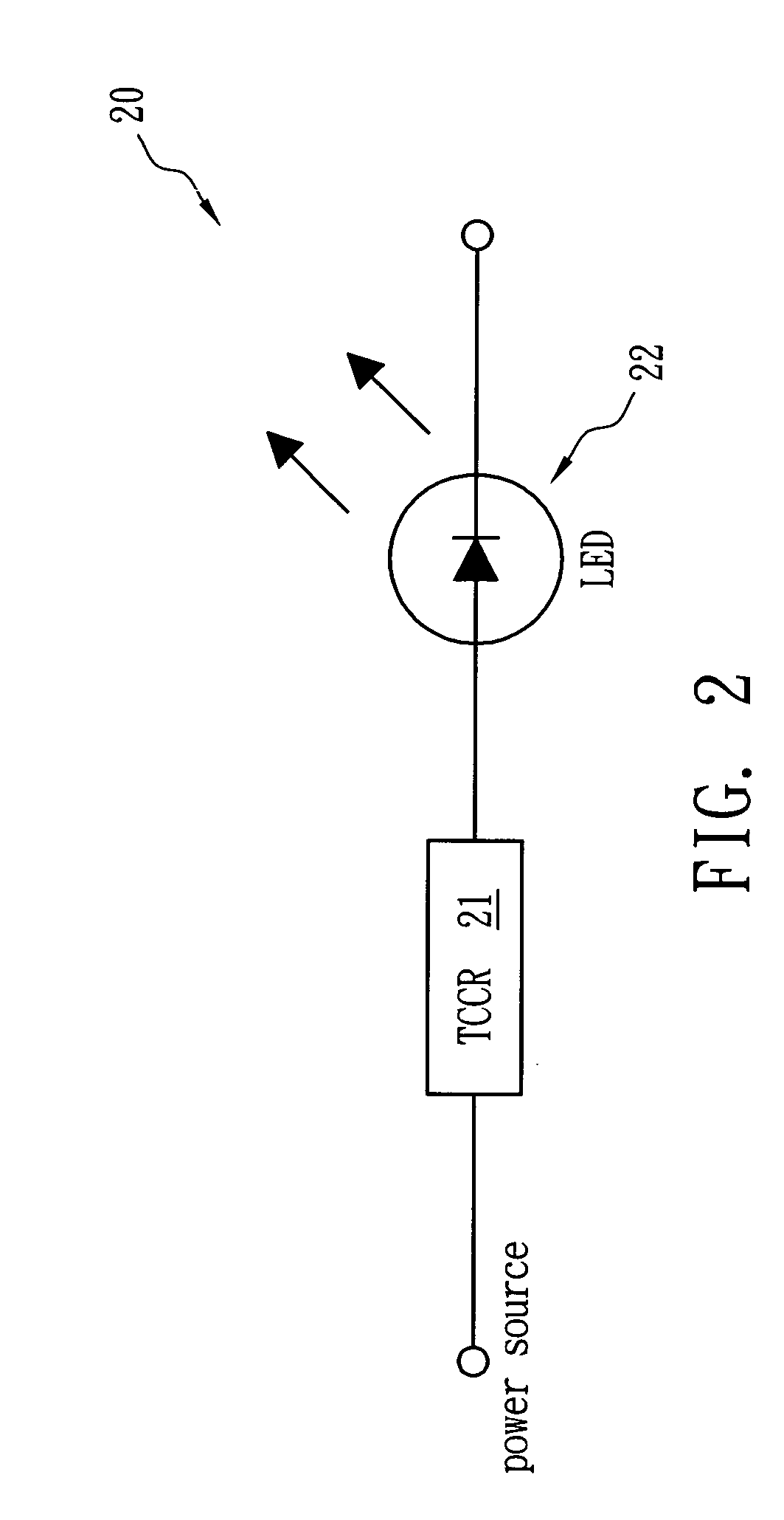
[0022]Referring to FIG. 2, an LED apparatus 20 of the present invention is formed by connecting a TCCR device 21 and an LED die 22 in series, and the interval between the TCCR device 21 and the LED die 22 is smaller than an effective sensing distance (e.g., 3 cm), such that the TCCR device 21 can effectively sense the temperature of the LED die 22.

[0023]The TCCR device 21 can be a PTC device, and the relationship between the resistance and the temperature of the TCCR device 21 is shown in FIG. 3. The resistance of the TCCR device 21 before tripping is in direct proportion to the temperature (e.g., 25° C.-85° C.) thereof, i.e., the resistance rises nearly linearly with temperature, and the resistance difference is greater than or equal to 100 mΩ when the temperature is between 50° C. -80° C. The resistance of the TCCR device 21 before tripping rises with temperature, so that when the temperature of the serially connected LED die 22 rises while emitting light, the TCCR device 21 will ...


PUM


Abstract

A light emitting diode (LED) apparatus with temperature control and current regulation functions is provided. The LED apparatus includes at least one LED die and at least one temperature control and current regulation (TCCR) device. The TCCR device is electrically connected between the LED die and a power source, and is placed within an effective temperature sensing distance of the LED die, so as to sense temperature changes of the LED die. The resistance of the TCCR device is proportional to the temperature in a range of 25° C. to 85° C., i.e., the resistance increases with temperature. Moreover, the resistance difference of the TCCR device between 50° C. and 80° C. is greater than or equal to 100 mΩ.

Description

BACKGROUND OF THE INVENTION[0001](A) Field of the Invention[0002]The present invention relates to a light emitting diode (LED) apparatus, and more particularly to an LED apparatus with temperature control and current regulation functions.[0003](B) Description of the Related Art[0004]In recent years, white LEDs have become a very popular new product attracting widespread attention all over the world. Because white LEDs offer the advantages of small size, low power consumption, long life, and quick response speed, the problems of conventional incandescent bulbs can be solved. Therefore, the applications of LEDs in backlight sources of displays, mini-projectors, illumination, and car lamp sources are becoming increasingly important in the market.[0005]Although LEDs represent the future of illumination applications, many problems still remain unsolved. For example, with a high power LED for illumination, only about 15-20% of input power is converted into light, and the remaining 80-85% ...

Claims


Application Information

Patent Timeline
Patent Type & Authority Applications(United States)
IPC IPC(8): H05B37/02
CPCH05B33/0872H05B45/28
Inventor WANG, DAVID SHAU CHEWYU, JYH MING
Owner POLYTRONICS TECH
Why Eureka
Try Eureka