Cryogenic Air Separation Process and Apparatus

a technology of cryogenic air and separation process, which is applied in the direction of lighting and heating apparatus, refrigeration and liquid storage, solidification, etc., can solve the problems of increasing the size and power consumption of the cosub>2 /sub>recovery unit, and becoming very costly and difficult to recover and capture the cosub>2 /sub>. , to achieve the effect o

Inactive Publication Date: 2008-05-22
LAIR LIQUIDE SA POUR LETUDE & LEXPLOITATION DES PROCEDES GEORGES CLAUDE +1
View PDF8 Cites 42 Cited by
  • Summary
  • Abstract
  • Description
  • Claims
  • Application Information

AI Technical Summary

Benefits of technology

[0038]iv) increasing the flowrate of the first air stream, feeding

Problems solved by technology

The diluted composition of CO2 increases the size and the power consumption of the CO2 recovery unit.
Because of this dilution, it becomes very costly and difficult to recover and capture the CO2 especially with the low pressure of the flue gas.
However, significant amount of heat is needed to regenerate the amine and to extract the CO2 such that the amine process is not cost effective.
For retrofitted oxycombustion coal plants, it is clear that the effort to capture CO2 is hindered by the cost of the oxygen plant.
Furthermore, the power consumption of the oxygen plant, which can be about 10% of the power plant output, also introduces additional cost issues: part of the power generated by the power plant must be diverted to supply the oxygen plant.
Therefore less power will be available to supply the grid, especially during peak demand when power is scarce and power costs are premium, resulting in reduction of power plant's revenue.
In this situation, the economics of CO2 capture and disposal by oxycombustion technique depend strongly on the cost and power consumption of the oxygen plant.
Without an efficient setup for the oxygen generation, the cost penalty would be such that it would become uneconomical to operate the clean and CO2-free oxycombustion power plants.
Since the CO of the fuel gas is combusted to yield CO2 in the burner of the gas turbine, the resulting CO2 is also mixed with the nitrogen of the gas turbine feed air such that the CO2 recovery is also a costly and difficult task.
The production of oxygen requires a

Method used


Image

  • Cryogenic Air Separation Process and Apparatus
  • Cryogenic Air Separation Process and Apparatus
  • Cryogenic Air Separation Process and Apparatus

Examples


Embodiment Construction

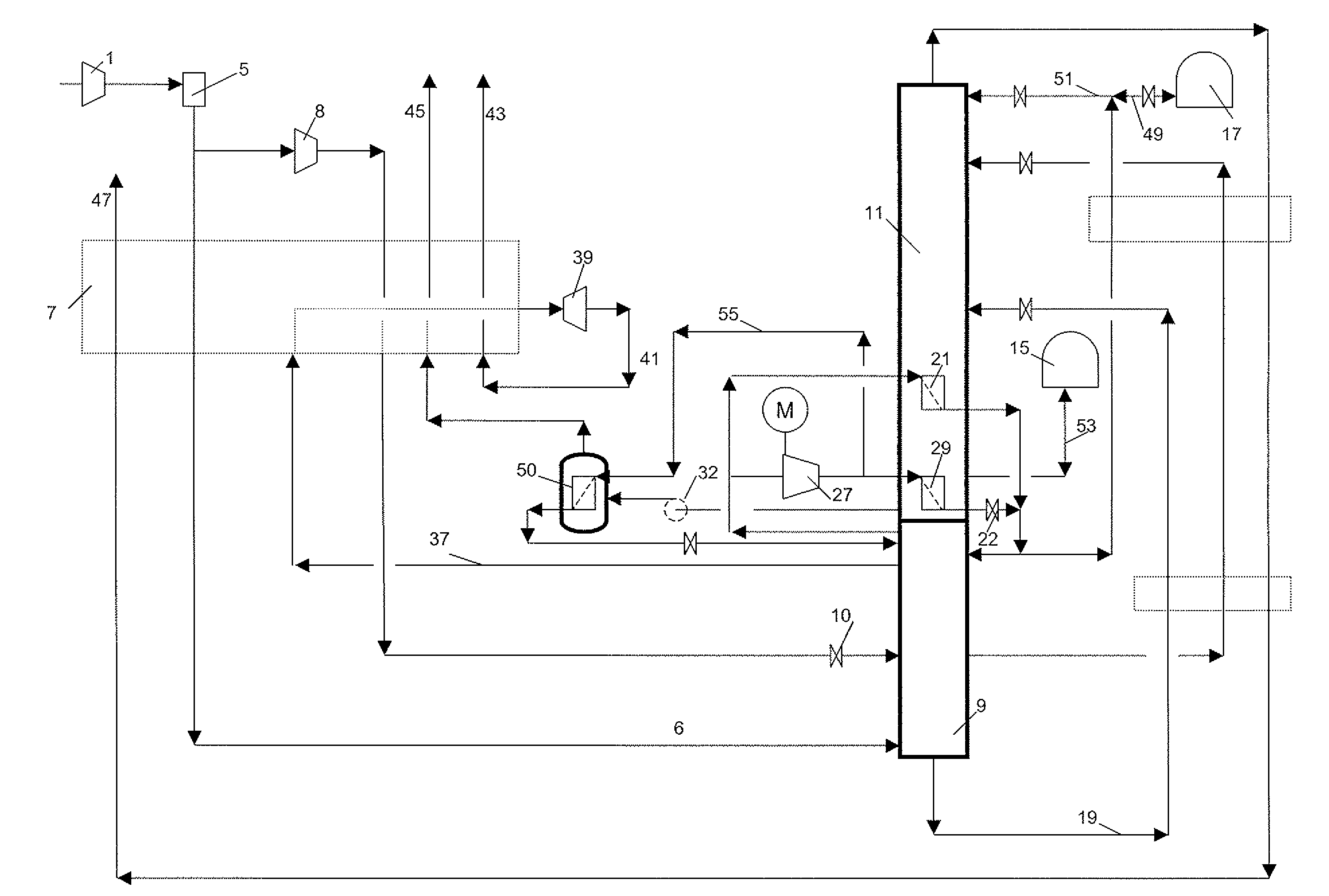
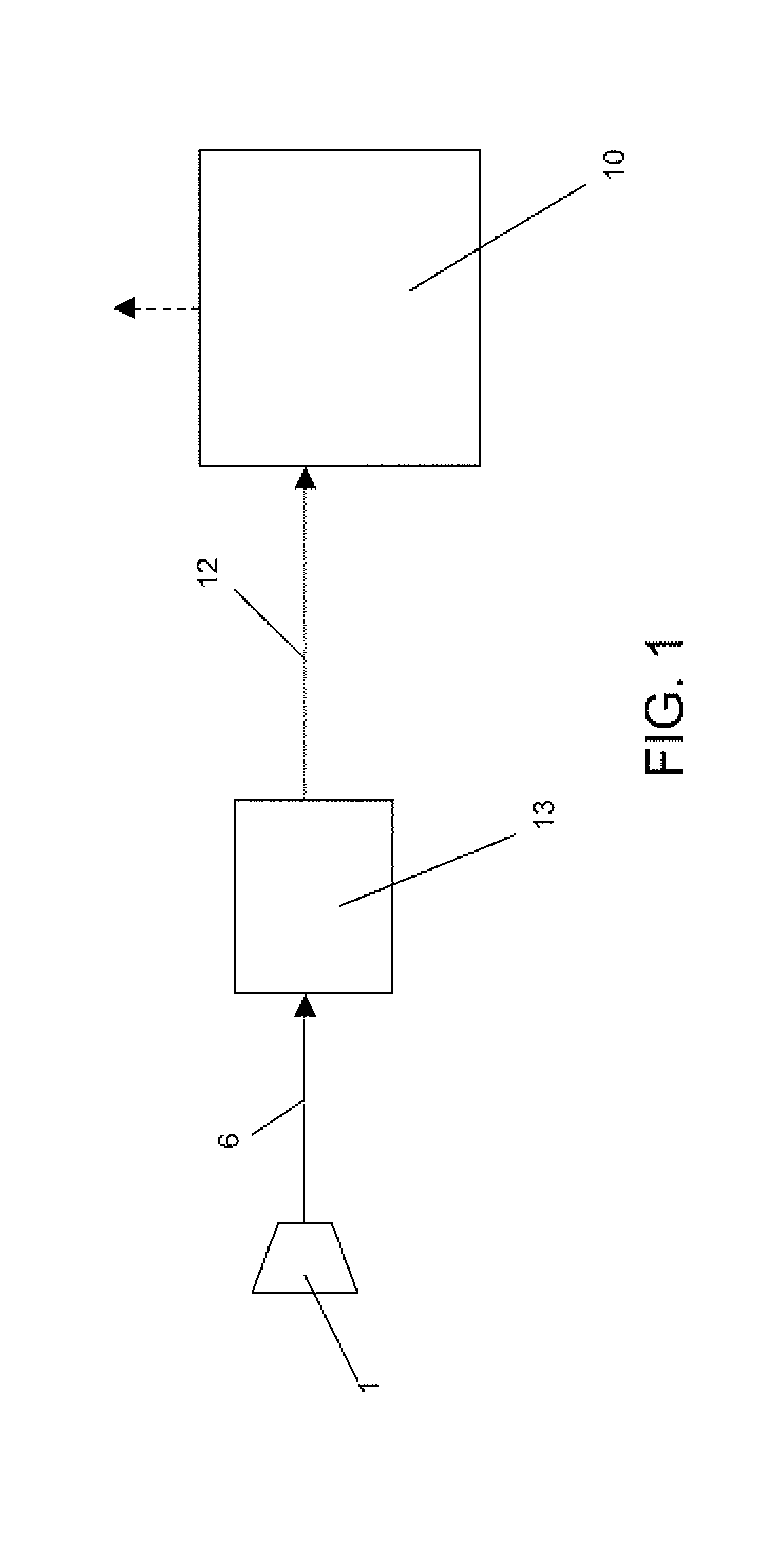
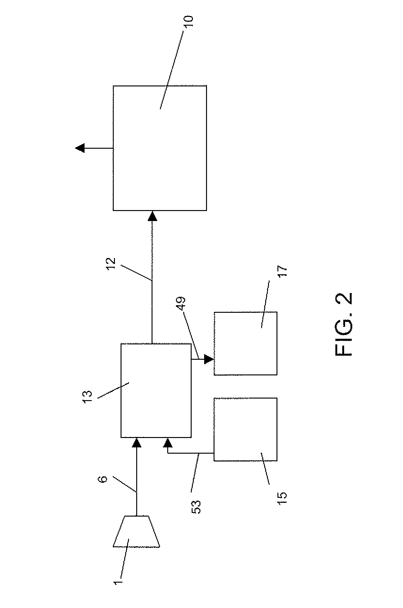
[0056]The invention will be described in greater detail with reference to the figures, wherein FIG. 1 represents the Prior art approach in which the air separation unit simply supplies the oxygen to the power plant. FIGS. 2 and 3 represent an air separation unit operating according to the invention at different periods, FIGS. 4 and 5 represent different phases of operation of plant according to the prior art and FIGS. 6, 7 and 8 represent an air separation units capable of operating according to the invention.

[0057]As shown on FIG. 1 for the Prior art, during peaks in power demand, 1000 Nm3 / h of feed air 6 is treated to yield 200 Nm3 / h of oxygen 12 required for peak demand by power generation plant 10. If the demand is reduced, less air is sent to the oxygen plant 13 to yield less oxygen. The air flow is essentially proportional to the oxygen demand.

[0058]As shown on FIG. 2 for the bascule approach, during peaks in power demand, 110 Nm3 / h of liquid oxygen 53 from a liquid oxygen tan...


PUM


Abstract

A cryogenic process for the production of oxygen by cryogenic distillation using an air separation unit comprising a double column, said double column comprising a high pressure column and a low pressure column comprising the steps of: sending compressed, cooled and purified air to the high pressure column in gaseous form, sending oxygen enriched fluid from the bottom of the high pressure column to the low pressure column, removing nitrogen enriched gas from the top of the high pressure column, sending a first portion of nitrogen enriched gas to a lower reboiler in the low pressure column following compression in a cold compressor having a cryogenic inlet temperature, sending a second portion of nitrogen enriched gas to an upper reboiler in the low pressure column, sending nitrogen enriched liquid from at least one of the first and second reboilers to at least one of the high pressure column and the low pressure column, expanding a stream of nitrogen enriched gas from the high pressure column in an expander following a warming step, driving the cold compressor using a motor and producing oxygen rich gas from the low pressure column by at least one of the steps of removing a gaseous stream and by vaporizing a liquid stream.

Description

BACKGROUND OF THE INVENTION[0001]The present invention relates to a cryogenic air separation process and apparatus.[0002]All pressures listed in the document are absolute pressures.[0003]Because of the global warming effect caused by the increased release of CO2 (carbon dioxide) generated by combustion processes, efforts have been made by utility companies and governments worldwide to reduce and minimize the CO2 emission. One major source of CO2 emission is the power generation plant's combustion process. There are mainly two types of power plants based on combustion processes: coal combustion and natural gas combustion. Both of these processes produce CO2 when generating power. The most efficient approach to reduce or minimize the CO2 emission is to capture most of the CO2 emitted by the power plants. For this effort to be efficient, it must also target the existing coal combustion plants that represent a large portion of the power generation plants worldwide. The oxy-combustion te...

Claims


Application Information

Patent Timeline
IPC IPC(8): F25J3/04
CPCF25J3/0406F25J2250/50F25J3/04212F25J3/04309F25J3/04351F25J3/04418F25J3/04509F25J3/04515F25J3/04545F25J3/04957F25J3/04969F25J2200/54F25J2230/22F25J2230/24F25J2230/40F25J3/0409
Inventor HA, BAOBRUGEROLLE, JEAN-RENAUD
Owner LAIR LIQUIDE SA POUR LETUDE & LEXPLOITATION DES PROCEDES GEORGES CLAUDE
Why Eureka
Try Eureka