Conductive membrane for carbon dioxide separation

a technology of carbon dioxide and conductive membrane, applied in the direction of membranes, separation processes, membranes, etc., can solve the problems of difficulty in technical implementation, loss of function as membranes, and difficulty in constructing apparatuses

Inactive Publication Date: 2008-05-22
SCHLUMBERGER TECH CORP +1
View PDF9 Cites 21 Cited by
  • Summary
  • Abstract
  • Description
  • Claims
  • Application Information

AI Technical Summary

Benefits of technology

[0014]In addition, the present invention provides a method of separating carbon dioxide from a gas mixture, including defining an injection region and a permeation region at both sides of a conductive membrane for carbon dioxide separation using a sealing material and a container, injecting inert gas, hydrogen, or inert gas containing hydrogen into the permeation region or maintaining the permeation region in a vacuum state, injecting the gas mixture containing carbon dioxide into the injection region, and collecting the separated carbon dioxide from a surface opposite the surface of the conductive membrane for carbon dioxide separation where the carbon dioxide is injected.

Problems solved by technology

Further, in the recovery of carbon dioxide from a great amount of exhaust gas, drastic reduction of energy consumption is required, but is presently difficult to technically implement.
However, this membrane is disadvantageous because selectivity for carbon dioxide is significantly decreased under conditions of temperature of 100° C. or higher, and the function as a membrane is lost, and it entails undesirable problems related to the process in which high-temperature combustion exhaust gas, which is a main carbon dioxide source, should be cooled to about room temperature to separate carbon dioxide therefrom.
In this case using the reverse reaction of a molten carbonate fuel cell, however, there are difficulties in constructing the apparatus, in which electrical power should be supplied from the outside through lead wires connected to opposite electrodes of the molten carbonate electrolyte.

Method used


Image

  • Conductive membrane for carbon dioxide separation
  • Conductive membrane for carbon dioxide separation
  • Conductive membrane for carbon dioxide separation

Examples


example 1

Manufacture of Conductive Membrane

[0037]A sintered perovskite oxide product, in which a molar fraction of La, Sr and Co is 0.6, 0.4 and 1.0, was produced.

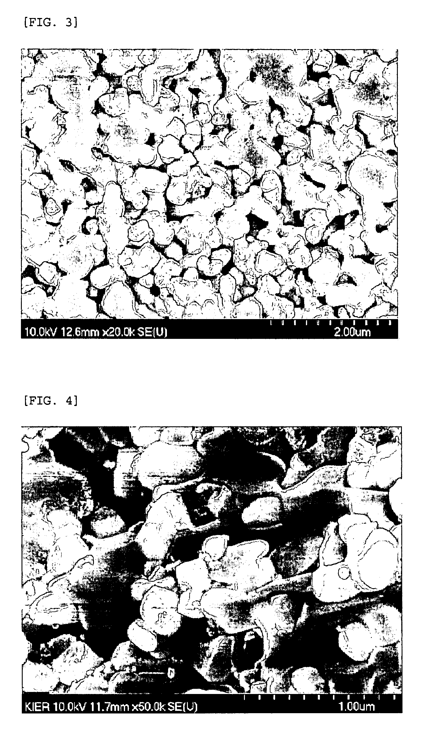
[0038]The power mixture, in which the molar fraction of La, Sr and Co is 0.6, 0.4 and 1.0, was maintained at 1000° C. for 2 hours or longer, thus forming a perovskite single phase, which was then compacted under pressure of 1 tonf using a disc-shaped mold having a diameter of 21 mm, and then sintered at 1050° C., thereby producing a sintered product.

[0039]FIG. 3 is a micrograph illustrating the electronically conductive oxide structure produced through heat treatment at 1050° C.

[0040]A carbonate mixture composed of Li2CO3 and K2CO3 at a molar ratio of 62:38 was molded and then attached to the surface of the electronically conductive oxide structure. Further, a molecule-ion exchange catalyst was applied on the outer surface of the molded carbonate product and the outer surface of the electronically conductive oxide structure.

[0041]T...

example 2

Separation of Gas Mixture using Conductive Membrane

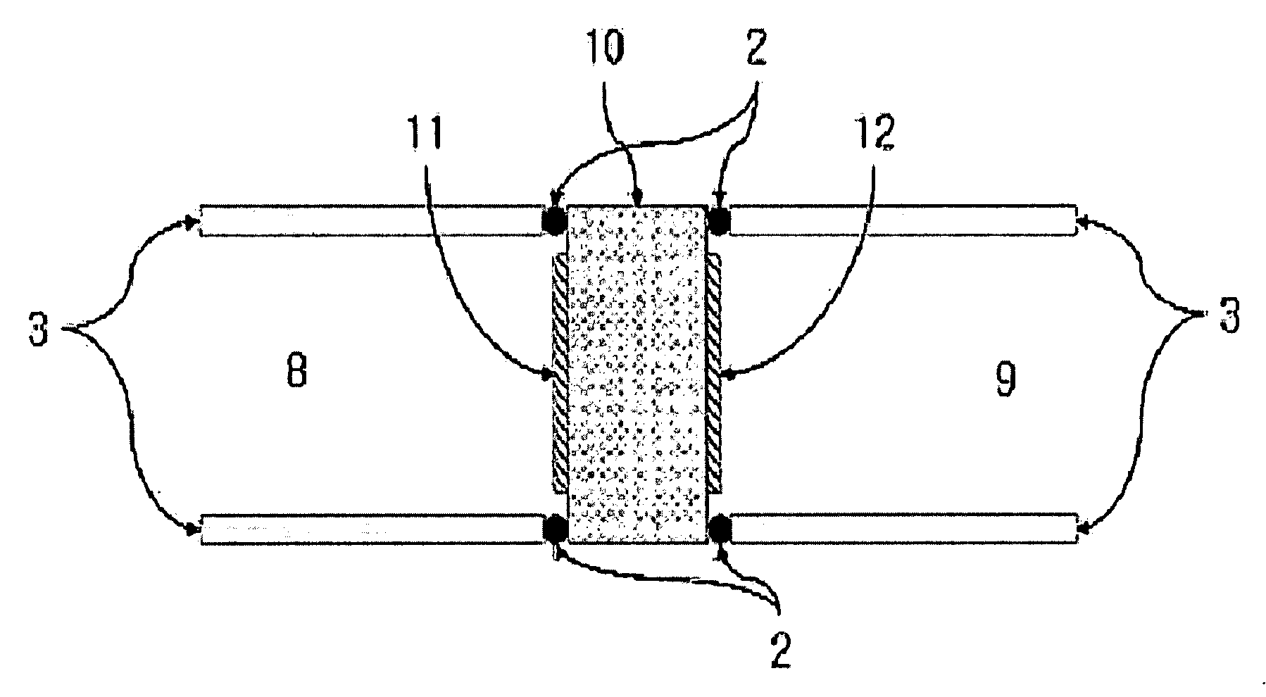
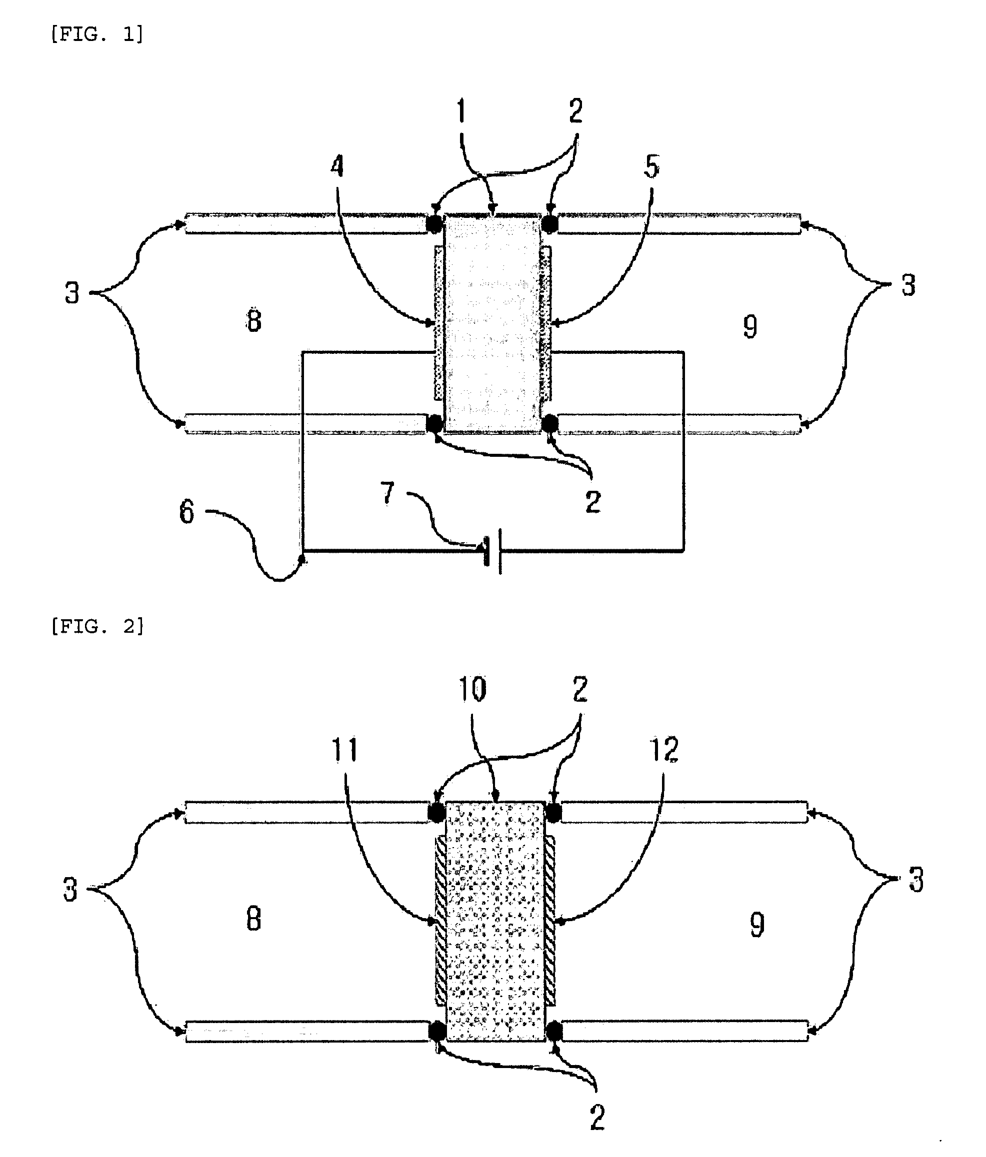
[0044]The conductive membrane manufactured in Example 1 was mounted between containers 3, as seen in FIG. 2, and an injection region 8 and a permeation region 9 were defined at both sides of the conductive membrane using a high-temperature sealing material 2. Carbon dioxide, oxygen and nitrogen were injected into the injection region, while inert gas, hydrogen or inert gas containing hydrogen was injected into the permeation region, or alternatively, the permeation region was maintained in a vacuum state, after which the membrane was maintained at 650° C.

[0045]The gases, which were separated through the conductive membrane and then discharged to the permeation region, were qualitatively and quantitatively analyzed using a gas analyzer, including gas chromatography. Among gases discharged from the permeation region, oxygen was condensed to water vapor through reaction with hydrogen, and only pure carbon dioxide was collected.

[0046]As...


PUM


Abstract

Disclosed are a conductive membrane able to selectively separate carbon dioxide from a gas mixture containing carbon dioxide, a manufacturing method thereof, and a method of separating carbon dioxide using the membrane. The conductive membrane for carbon dioxide separation includes molten carbonate, acting as a carbonate-ion conductor, and oxide, acting as an electronic conductor, and has infinite selectivity for carbon dioxide at high temperatures of 500° C. or more.

Description

BACKGROUND OF THE INVENTION[0001]1. Field of the Invention[0002]The present invention relates to a conductive membrane that is able to selectively separate only carbon dioxide from a gas mixture containing carbon dioxide, to a method of manufacturing the same, and to a method of separating carbon dioxide using the membrane. According to the present invention, the conductive membrane for carbon dioxide separation includes molten carbonate, acting as a carbonate-ion conductor, and oxide, acting as an electron conductor, and has infinite selectivity for carbon dioxide at high temperatures of 500° C. or more.[0003]2. Description of the Related Art[0004]The ambient concentration of carbon dioxide, which is one of the main causes of global warming, is increasing at a rate of 1 or more ppm every year, attributable to the consumption of fossil fuels, and thus, techniques for the effective treatment thereof are regarded as very important in the interest of energy resources and the environmen...

Claims


Application Information

Patent Timeline
Patent Type & Authority Applications(United States)
IPC IPC(8): B01D53/22B05D3/02B01D67/00
CPCB01D53/228B01D67/0074Y02C10/10B01D71/024B01D2325/10B01D69/141Y02C20/40B01D71/0271B01D2257/504
Inventor LEE, SHIWOOWOO, SANG KUKYU, JI HAENGSEO, DOO WONHONG, KI SUKHAN, IN SUBKIM, SE YOUNG
Owner SCHLUMBERGER TECH CORP
Why Eureka
Try Eureka