Method Of Manufacturing A Molding With A Core

a manufacturing method and molding technology, applied in the direction of manufacturing tools, pharmaceutical product form changes, applications, etc., can solve the problems of insufficient strength of a portion of the outer layer forming insufficient packaging density of the molding material supplied in this part, etc., to achieve enhanced and sufficient strength, the effect of enhancing the strength of the sidewall of the molding

Inactive Publication Date: 2008-05-22
SANWAKAGUKU KENKYUSHO CO LTD +1
View PDF34 Cites 6 Cited by
  • Summary
  • Abstract
  • Description
  • Claims
  • Application Information

AI Technical Summary

Benefits of technology

[0011]The inventors of the present invention have solved the aforementioned problem by increasing the amount of the molding material for the outer layer to be supplied into the space between the outer layer and core molding and the lower outer punch in the outer layer supply step 2. Specifically, the outer layer supply step 2 of supplying the molding material for the outer layer into the space defined above and around the aforementioned outer layer and core molding, that is, the step of supplying the molding material for the outer layer (the last outer layer supply step) posterior to the step of supplying the molding material for the core is performed until the tip of the lower center punch finally takes a position protruding from the tip of the lower outer punch by further lowering the lower outer punch tip, whereby the packing density of the molding material for the outer layer forming the sidewall of the molding can be increased and, hence, the strength of a portion of the outer layer that forms the sidewall of the molding can be enhanced.
[0016]An essential feature of the present invention is that the step of supplying the molding material for the outer layer, which follows the step of supplying the molding material for the core, is performed until the tip of the lower center punch finally takes a position protruding from the tip of the lower outer punch, and then the step of compression-molding the whole molding is performed with the tips of the lower center punch and the lower outer punch aligned with each other. This feature gives rise to the effect of enhancing the strength of the sidewall of the molding and / or the effect of allowing the manufacture of a molding with a core to be achieved through the step of supplying molding material performed twice.
[0017]In a case of the present invention, it is possible to obtain a molding with a core having a enhanced and sufficient strength in a portion of the outer layer forming the sidewall thereof when the molding with a core is manufactured by the method using compression molding means having an upper and a lower punch and a die, both of the upper punch and the lower punch having a double structure comprising a center punch and an outer punch surrounding the outer periphery of the center punch, and being slidable and capable of a compressing operation. In another case of the present invention, it is possible to eliminate the outer layer supply step 1 preceding the step of supplying the molding material for the core, because the last supplied molding material for the outer layer is led to under the outer layer and core molding. Hence, the molding with a core can be manufactured through the step of supplying molding material performed twice. In the method of manufacturing a molding with a core through the step of supplying molding material performed twice, it is possible to manufacture a molding with a core while enhancing the strength of a portion of the outer layer forming the sidewall of the molding. Further in another case of the present invention, the aforementioned phenomenon that the molding material for the outer layer is led to under the outer layer and core molding provides no boundary between a portion of outer layer forming the bottom of the molding and a portion of outer layer forming the sidewall of the molding, thus making it possible to prevent contamination of the molding material for the core which would otherwise occur frequently in the conventional manufacturing method on the bottom surface of the molding due to the provisionally molded core shaved during the preparation process.

Problems solved by technology

In other words, the amount of molding material for the outer layer supplied into the space around the temporary molding of the outer layer and the core, that is, the space defined between the outer layer and core molding and the lower outer punch is equivalent to the thickness of the temporary molding of the outer layer and the core and, for this reason, the packing density of the molding material for the outer layer supplied in this part is insufficient.
It was therefore found out that the strength of a portion of the outer layer forming the sidewall of the molding was sometimes insufficient.

Method used


Image

  • Method Of Manufacturing A Molding With A Core
  • Method Of Manufacturing A Molding With A Core
  • Method Of Manufacturing A Molding With A Core

Examples


example 1

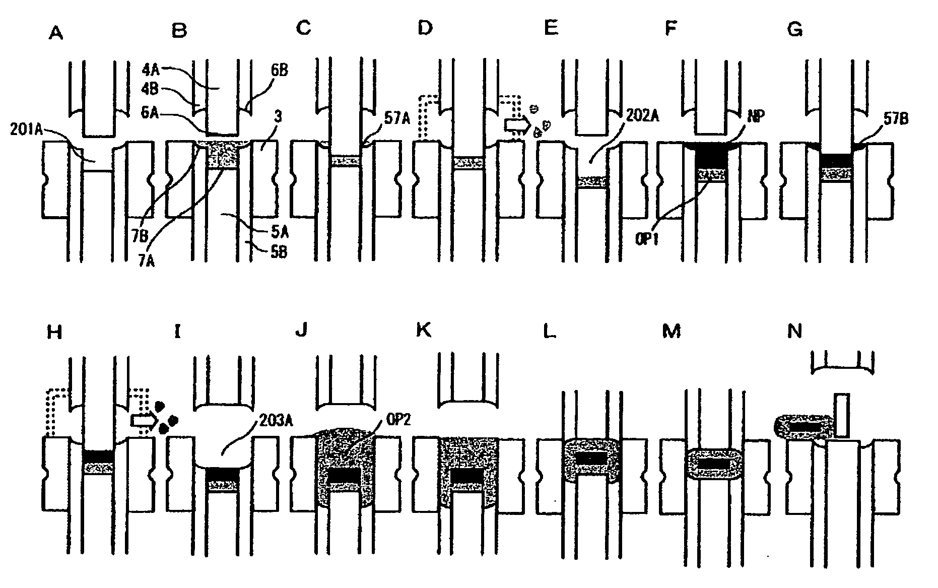
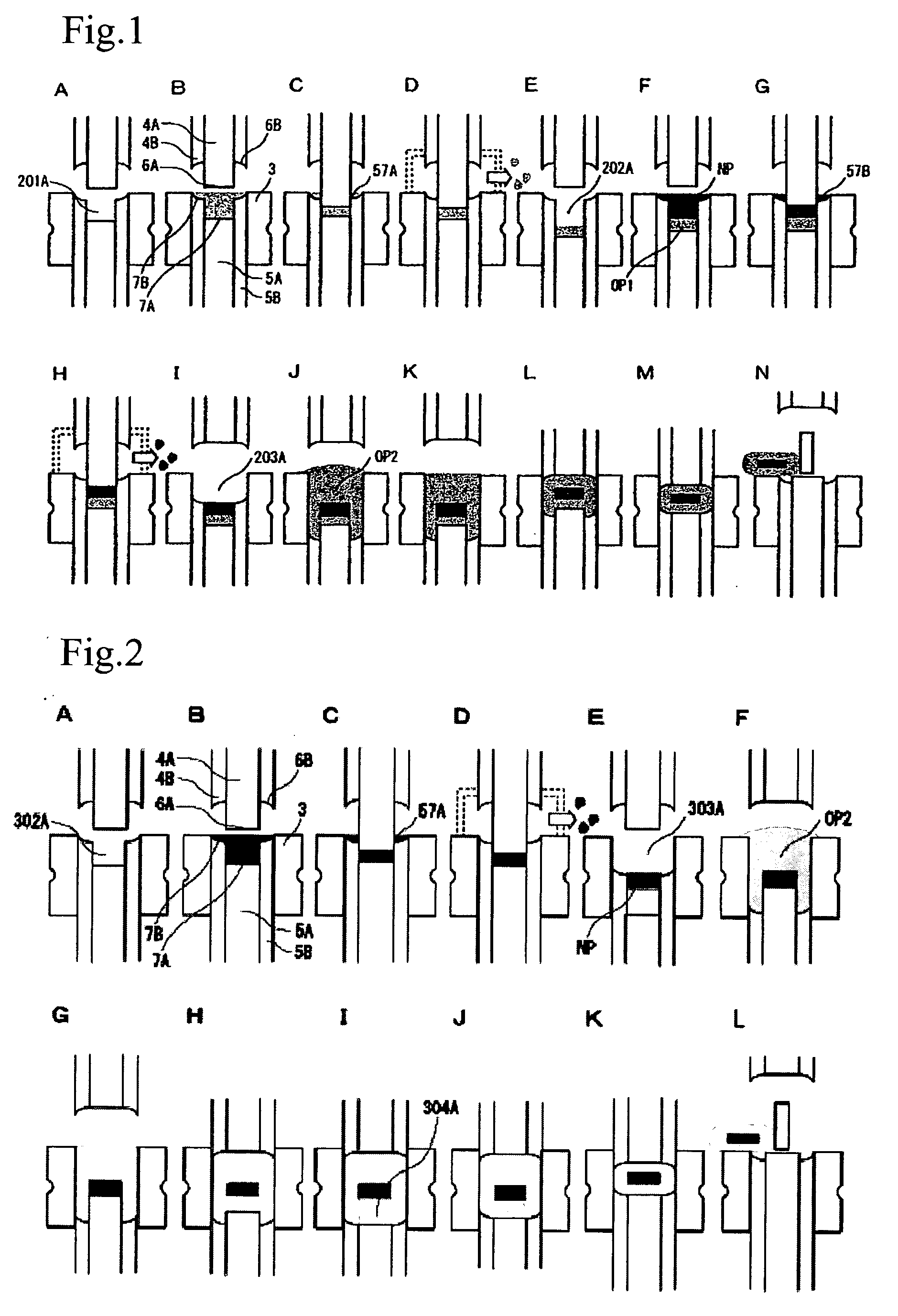
[0062]Hereinafter, examples of the present invention will be described including: example 1 in which the formability of a molding with a core was improved by improving the packing density of the molding material for the outer layer; and examples 2 to 4 as manufacture examples of a molding with a core in each of which the molding material for the outer layer was supplied and led.

manufacture example 1

[0063]A small amount of magnesium stearate (produced by TAIHEI CHEMICAL INDUSTRIAL CO., LTD.) was applied to the surfaces of respective of upper and lower punches each of which had a double structure with an inner diameter of 5 mmφ, an outer diameter of 8 mmφ and a flat bevel and was capable of pressing. With the lower center punch in a lowered position, 30 mg of a spray-dried product of lactose-crystalline cellulose (“Microcellac” produced by MEGGLE hereinafter will be referred to as molding material A) was supplied into the space defined above the lower center punch and enclosed by the lower outer punch. The upper center punch and the lower center punch were then moved toward each other and temporary compression was performed manually on the molding material A to such an extent as to flatten the surface of the molding material A, thus giving a temporary molding of the first outer layer. Subsequently, with the lower center punch in a lowered position, 100 mg of mixed powder consist...

experimental example 1

(a) Evaluation of tablet hardness

[0065]The tablet hardness of each of the tablets obtained by manufacture example 1 and comparative manufacture example 1 was evaluated by measuring the maximum stress at destruction on each of the tablets pressed diametrically by means of a rheometer (manufactured by SUN SCIENTIFIC CO., LTD.). The results were as shown in Table 1.

(b) Evaluation of Friability

[0066]The friability of each of the tablets obtained by manufacture example 1 and comparative manufacture example 1 was evaluated by using a motor-driven drum (ELECTROLAB:EF1-W) according to a test method of determining the friability test of tablet (equivalent to USP24 General / information TABLET FRIABILITY) as reference information in Japanese Pharmacopoeia, 13th revision, second addenda. The results were as shown in Table 1.

TABLE 1COMPARATIVE MANUFACTUREMANUFACTURE EXAMPLE 1EXAMPLE 1AMOUNT OF DESCENT OFEVALUATIONAMOUNT OF DESCENT OF THETHE LOWER OUTER PUNCHITEMLOWER OUTER PUNCH 0 mm3 mmTABLET61...


PUM

PropertyMeasurementUnit
outer diameteraaaaaaaaaa
universal tension and compression testeraaaaaaaaaa

Abstract

The present invention provides a method for manufacturing a molding with a core by using compression molding means having upper and lower double-structured punches; the method comprising the steps of supplying molding material for the core and molding material for the outer layer respectively, the step of compression-molding the molding material for the core and / or the molding material for the outer layer, and the step of compression-molding the whole molding with a core, wherein: the step of supplying the molding material for the outer layer posterior to the step of supplying the molding material for the core is performed until a tip of the lower center punch finally takes a position protruding from a tip of the lower outer punch; and the step of compression-molding the whole molding with a core is performed with the tips of the lower center punch and the lower outer punch aligned with each other. This method can be expected to bring about the effect of enhancing the strength of a portion of outer layer forming the sidewall of the molding and / or the effect of allowing the molding material for the outer layer supplied after the step of supplying the molding material for the core to be led to under the temporary molding of the core thereby making it possible to manufacture a molding with a core through the molding material supply step performed twice.

Description

TECHNICAL FIELD[0001]The present invention relates to a method of manufacturing a molding by compression of such a molding material as powder granule and, more specifically, to a method of manufacturing a molding with a core by using punches of a double structure.BACKGROUND ART[0002]A method of manufacturing a molding by compressing and solidifying molding material, a representative of which is powder granule etc., is generally used in a wide range of industry including, for example, not only industrial fields of pharmaceuticals and foods (functional foods and general foods) but also electronic material fields such as molding of semiconductor encapsulating resin, battery-related products, powder metallurgy-related products, electronic functional parts and the like, and fields of agricultural chemicals and sanitary products.[0003]In the field of pharmaceuticals, among formulations for oral administration in particular, a solid molding called “tablet” is presently one of the most wide...

Claims


Application Information

Patent Timeline
Patent Type & Authority Applications(United States)
IPC IPC(8): B30B11/00A61J3/10B30B11/34
CPCB30B11/34A61J3/10B30B11/02B30B11/00A61J3/06A61J3/07
Inventor OZEKI, YUICHIIZUMI, KENTAROHARADA, KENJI
Owner SANWAKAGUKU KENKYUSHO CO LTD
Why Eureka
Try Eureka