Image projecting apparatus and image projecting method

a projecting apparatus and image technology, applied in the field of image projecting apparatus and image projecting method, can solve the problems of reducing resolution, affecting image quality, and affecting image quality,

Inactive Publication Date: 2008-05-22
RICOH KK
View PDF14 Cites 12 Cited by
  • Summary
  • Abstract
  • Description
  • Claims
  • Application Information

AI Technical Summary

Benefits of technology

[0009]It is a general object of the present invention to provide a novel and useful ...

Problems solved by technology

In order to address such demand, one important issue is how to reduce the size or weight of the projection lens forming the projection optical system.
However, reducing the number of the individual lenses generally results in a decrease in resolution, or degradation in imaging properties in terms of, e.g., distortion, chromatic aberration of magnification, and aberration.
However, such methods are still associated with the problem of...

Method used


Image

  • Image projecting apparatus and image projecting method
  • Image projecting apparatus and image projecting method
  • Image projecting apparatus and image projecting method

Examples


embodiment 1

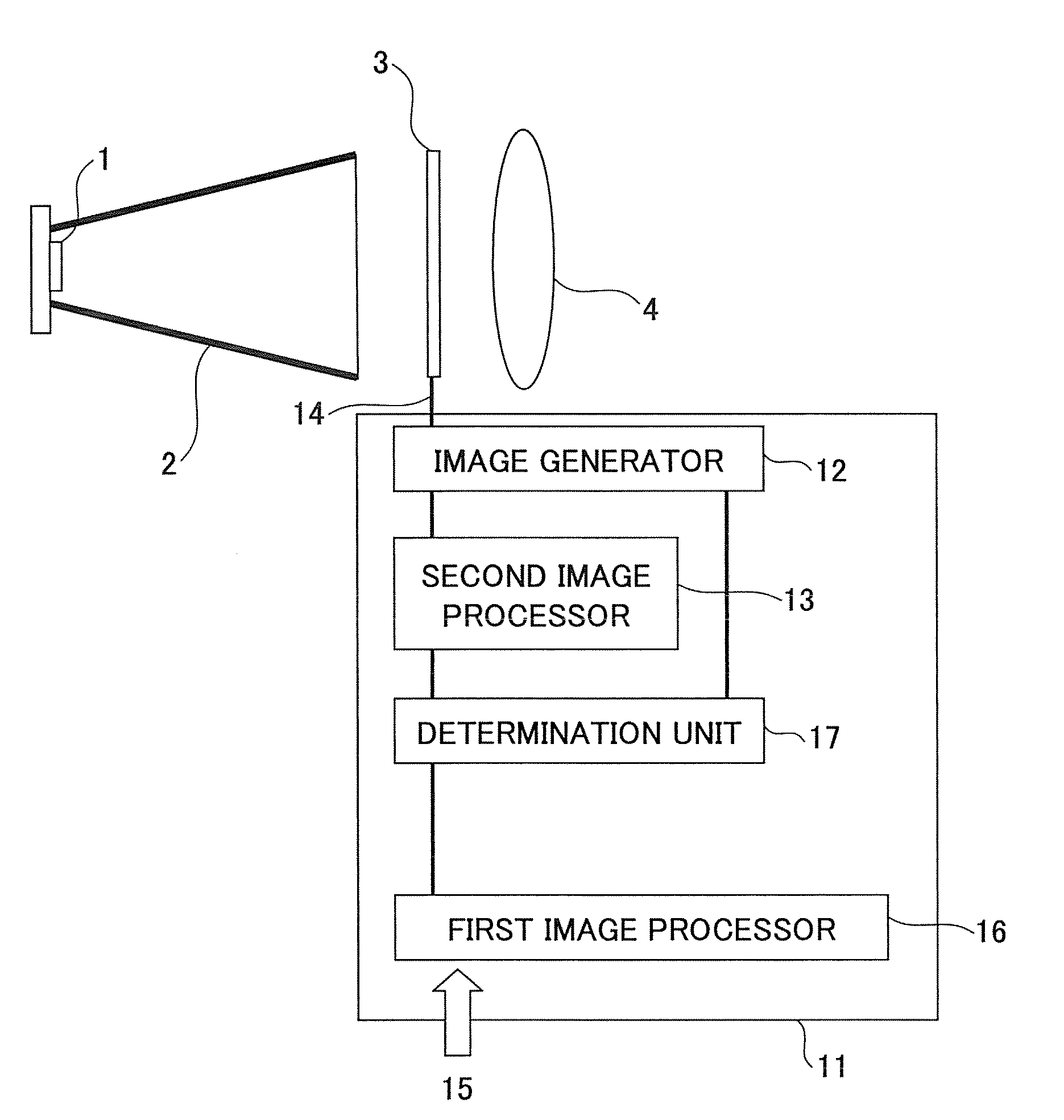
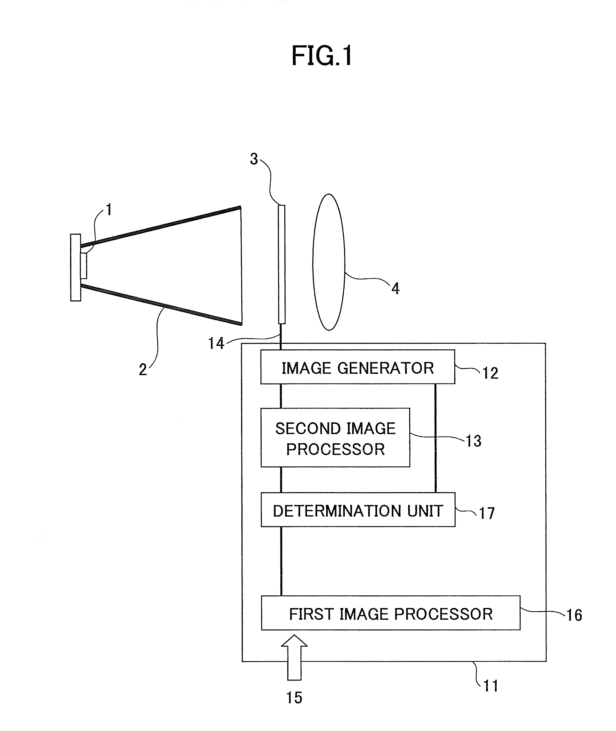
[0043]FIG. 1 shows a diagram of an image projecting apparatus (“projector”) according to a first embodiment of the invention. The projector comprises a light source 1, a rod integrator 2, a liquid crystal light modulating device 3, and a projection lens 4. An image signal 14 carrying image information fed to the liquid crystal light modulating device 3 on an individual pixel region basis is supplied from an image processing device 11. The image processing device 11 comprises a first image processor 16, a determination unit 17, a second image processor 13, and an image generator 12. The image processing device 11 processes an original image 15, i.e., the externally entered image information, and outputs the image signal 14.

Light Source

[0044]The light source 1 is composed of plural light-emitting diodes (“LEDs”) that are arranged, e.g., two-dimensionally. The light source 1 is preferably configured such that the light-emitting portions of the LEDs are housed within the rod integrator ...

embodiment 2

[0054]In Embodiment 2, a projector is described that comprises a second image processor employing a different image processing method from the second image processor of Embodiment 1. The present embodiment provides an image projecting method and apparatus whereby, as in the foregoing Embodiment 1, a pixel region that is determined by the determination unit to contain image information that has overflowed or underflowed is subjected to image processing in the second image processor. Specifically, the second image processor substitutes an overflow or an underflow region with an upper limit or a lower limit of the representable range of the light modulating device. Based on the image information thus processed in the second image processor, the flux of light from the illumination optical system is modulated by the light modulating device. The modulated flux of light is projected by the projection optical system on a screen to form a projected image.

Second Image Processing

[0055]With ref...

embodiment 3

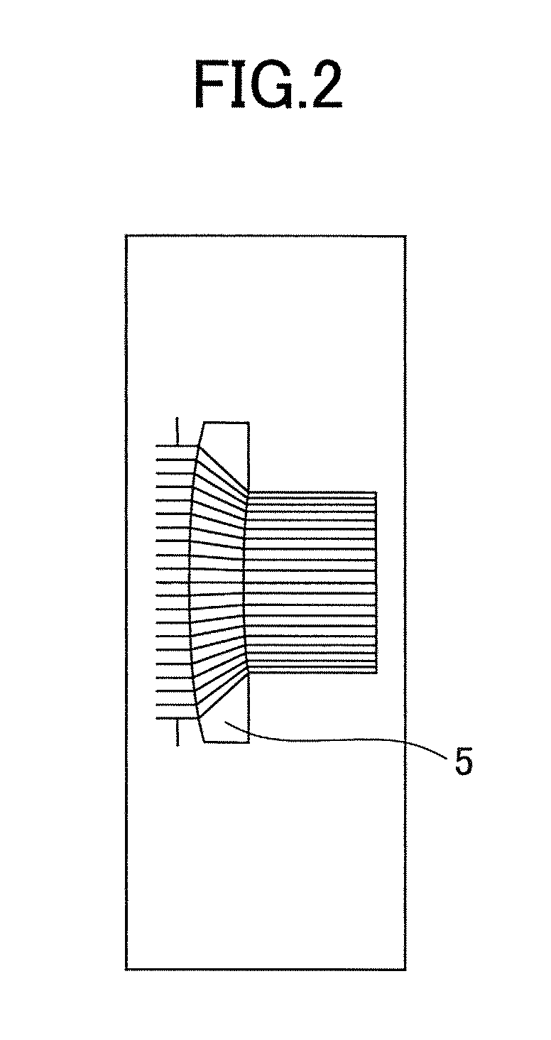
[0058]In Embodiment 3, the illumination optical system of the projector of Embodiment 1 is additionally provided with a device to control the distribution of light amount. The light-amount distribution controller may comprise a device to achieve a uniform light amount, such as the already-described rod integrator, which equalizes the distribution of light amount in a cross section perpendicular to the flux of light. Preferably, the illumination optical system also comprises, in addition to the aforementioned light-amount equalizer, a light-amount distribution converter for obtaining a light-amount distribution such that, in a cross section perpendicular to the flux of light, the light amount increases from the optical axis center toward the peripheral portion. One example of such a light-amount distribution converter is a light-amount distribution conversion element 5 shown in FIG. 2. Conventional illumination optical systems have been configured such that the light modulating devic...


PUM


Abstract

An image projecting apparatus enables the formation of a projected image faithful to original image information by reducing degradation in the projected image due to decrease in imaging performance of a projection optical system. Image information is processed by an image processing device, which includes a first and a second image processor. A light modulating device modulates a flux of light emitted by an illumination optical system based on the processed image information. The modulated flux of light is projected on a screen by a projection optical system. If the image information processed by the first image processor in a pixel region is not within a representable modulation range of the light modulating device, the image information is processed by the second image processor.

Description

BACKGROUND OF THE INVENTION[0001]1. Field of the Invention[0002]The present invention relates to an image projecting apparatus and an image projecting method.[0003]2. Description of the Related Art[0004]As a result of the growth of electronic information media, there are increasing occasions where an image projecting apparatus (also referred to as “a projector”) is utilized. A typical projector comprises an illumination optical system including a light source, and a light modulating device, such as a liquid crystal light valve, that modulates a flux of light emitted by the illumination optical system in accordance with image information that is entered externally. It also comprises a projection optical system, such as a projection lens, for projecting the flux of light modulated by the light modulating device on a screen as an enlarged image. Among others, a liquid crystal projector that employs an LCD device as a light modulating device is well-known. The liquid crystal projector, ...

Claims


Application Information

Patent Timeline
IPC IPC(8): G03B21/20G06T1/20
CPCG03B27/545H04N5/74H04N5/7416H04N9/3102H04N9/3152H04N9/3173G03B21/208H04N9/3197H04N9/73H04N2005/745G03B21/2013G03B21/2033H04N9/3179
Inventor HAMANO, YUKIKOKASAHARA, RYOSUKEKAWASAKI, TOSHIYUKI
Owner RICOH KK
Why Eureka
Try Eureka