Laser diode driver with multiple modulation current source

a technology of laser diodes and current sources, applied in the field of laser diodes, can solve the problems of difficult precise control of bipolar devices, difficult to precisely control bipolar devices, etc., and achieve the effect of suppressing the influence of resonance oscillation and improving the waveform of optical outpu

Active Publication Date: 2008-05-22
SUMITOMO ELECTRIC IND LTD
View PDF1 Cites 17 Cited by
  • Summary
  • Abstract
  • Description
  • Claims
  • Application Information

AI Technical Summary

Benefits of technology

[0009]In the LD-driver according to the invention, the modulation current supplied to the LD is superposed with respective currents output from the switched current source, and the amplitude, the phase and the pulse width may be varied independent to each other. Therefore, even when the switched current source is constituted with current controlled devices such as bipolar transistor, the waveform of the modulation current may be optionally adjusted so as to improve the waveform of the optical output from the LD. The LD-driver of the invention may be applicable to a signal source for the long-reach optical communication; because the LD-driver may effectively suppress the influence of the resonance oscillation of the LD appeared in the leading edge of the modulation current.

Problems solved by technology

On the other hand, the bipolar device, typically a bipolar transistor with a current controlled configuration, seems to be hard to precisely control, in other words to control in analogue, the current flowing in the device because of their large trans-conductance.

Method used


Image

  • Laser diode driver with multiple modulation current source
  • Laser diode driver with multiple modulation current source
  • Laser diode driver with multiple modulation current source

Examples


Embodiment Construction

[0025]Next, preferred embodiments of the present invention will be described in detail as referring to accompanying drawings. In the description of drawings, the same numerals or symbols will refer to the same elements without overlapping explanations.

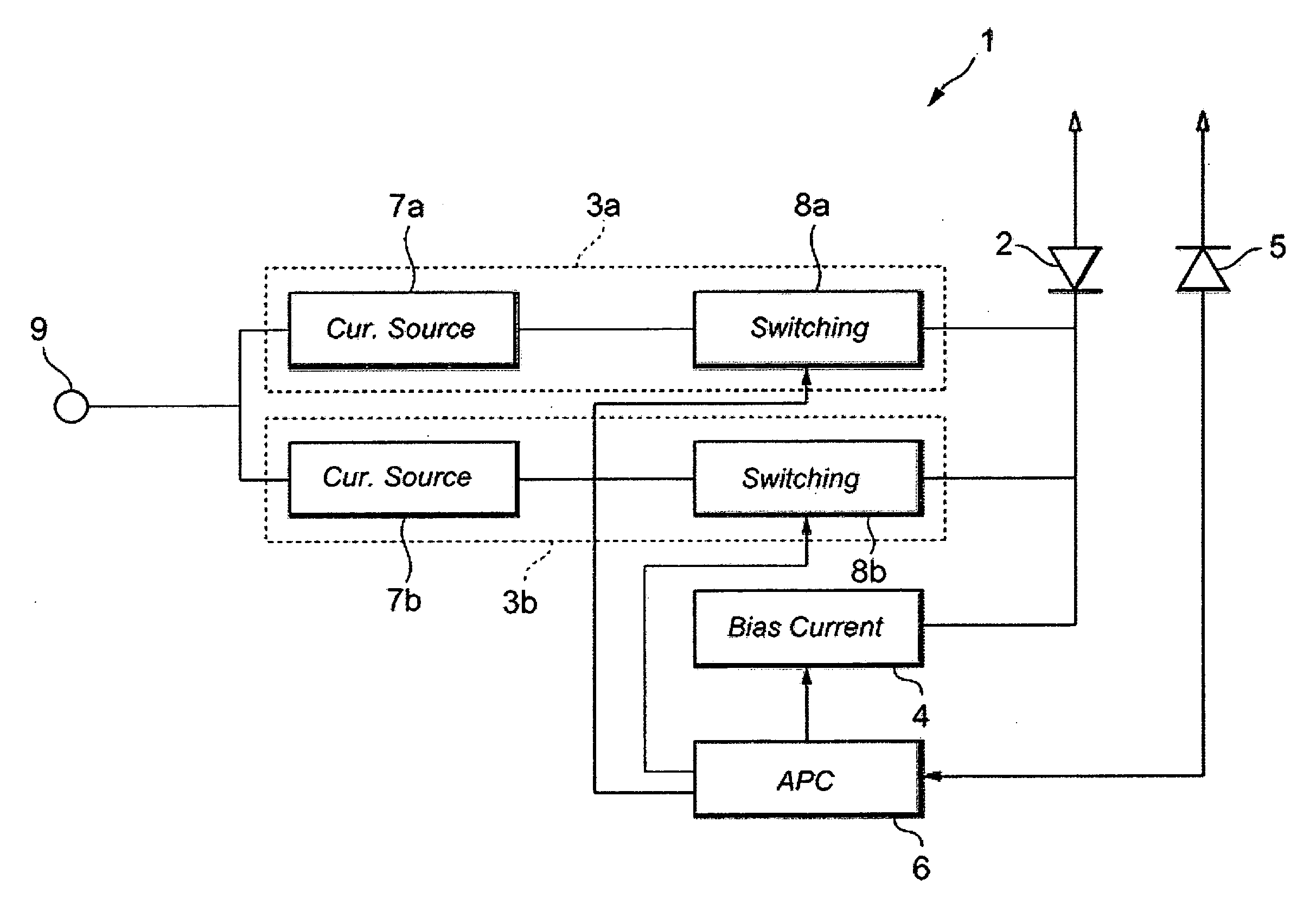
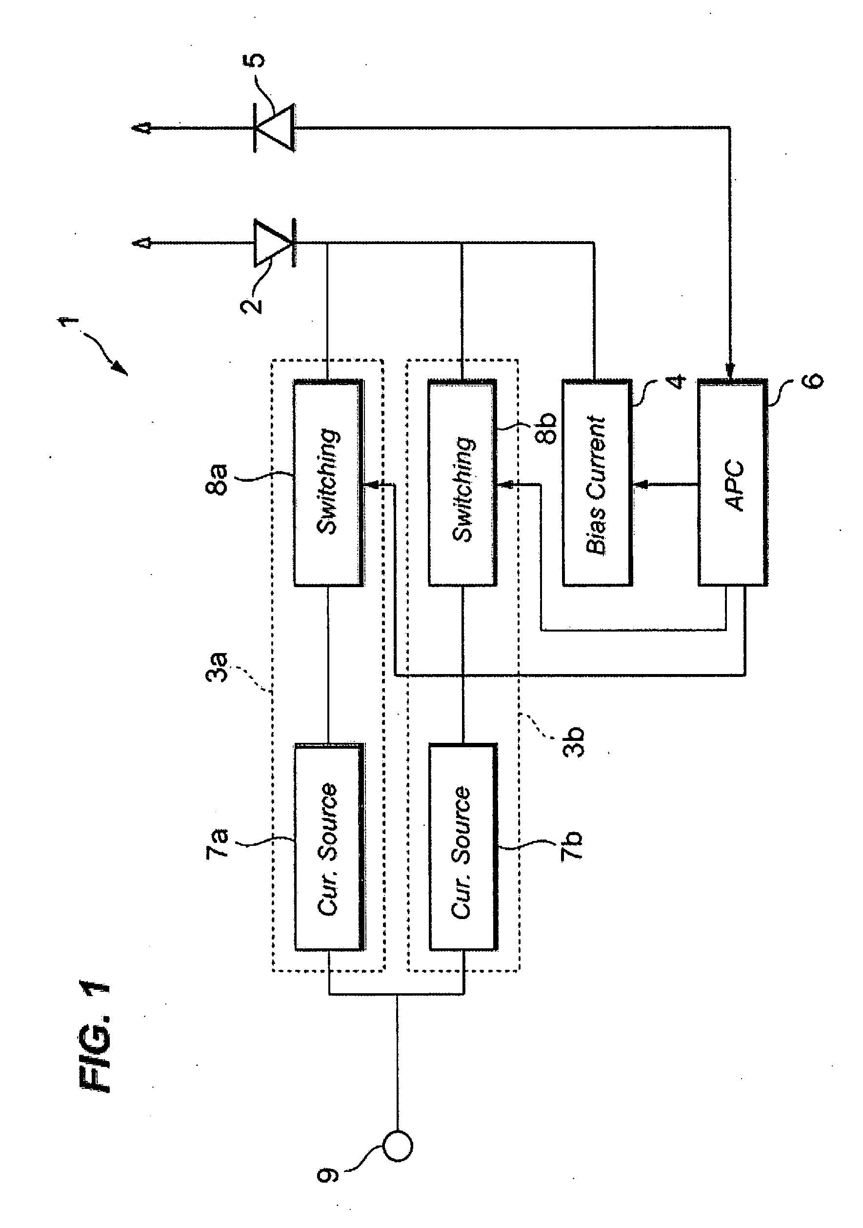
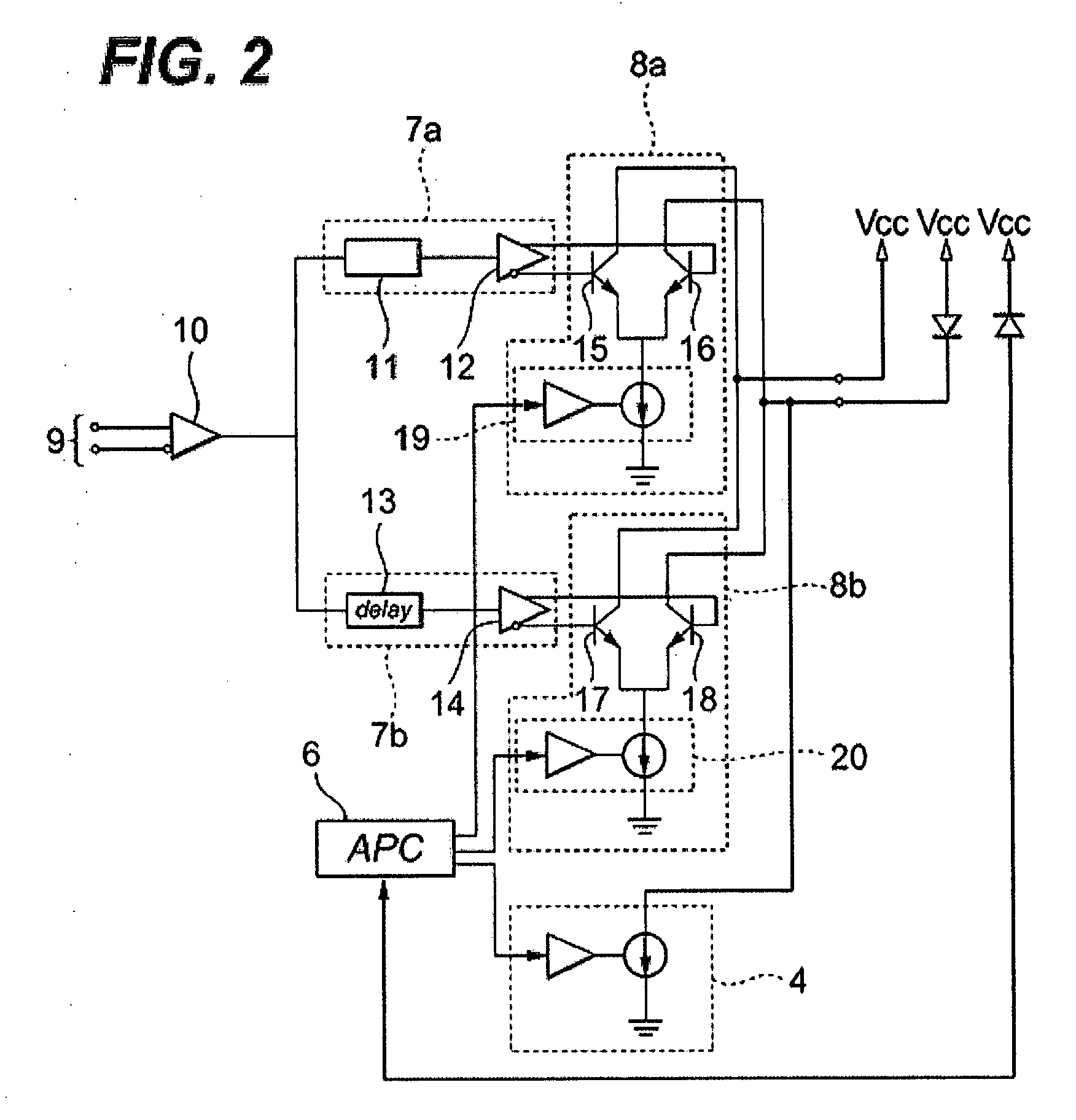
[0026]FIG. 1 is a block diagram of the LD-driver according to an embodiment of the present invention, and FIG. 2 is a circuit diagram of the LD-driver shown in FIG. 1. The LD-driver 1, which is installed within an optical transmitter for the optical communication system, drives a light-emitting device such as a semiconductor laser diode (hereafter denoted as LD). As shown in FIG. 1, the LD-driver 1 includes two modulation current sources, 3a and 3b, a bias current source 4, a photodiode 5 for monitoring an optical output emitted from the LD2, and an Auto-Power Control (hereafter denoted as APC) circuit 6.

[0027]The modulation current sources, 3a and 3b, supply a modulation current to the LD 2, and each includes a pre-amplifier, 7a or 7b...


PUM


Abstract

The present invention is to provide an LD-driver that enables to adjust the waveform of the driving current to the LD even the driver is constituted with a current controlled device such as bipolar transistor. The LD-driver of the invention provides a plurality of modulation current sources each having a function to set the amplitude, the phase and the pulse width of the current output independently. The LD is provided with the modulation current superposed with each current derived from respective current sources.

Description

BACKGROUND OF THE INVENTION[0001]1. Field of the Invention[0002]The present invention relates to a laser diode driver (LD-driver) to drive a semiconductor laser diode (hereafter denoted as LD).[0003]2. Related Prior Art[0004]The LD-driver drivers the LD by receiving a driving signal and applying a modulation current modulated by the received driving signal. A conventional LD-driver usually includes a modulation current source and a bias current source with a current switching circuit operated by the driving signal. Supplying the driving sigal with a differential mode to the current switching circuit with a paired transistor to switch the current. from the current source, the optical output from the LD may be modulated in accordance with the driving signal.[0005]Japanese Patent Application published as JP-S60-187075A has disclosed a driver circuit for the LD, where one of the inputs of the differential circuit provides a capacitor to suppress the relaxation oscillationoftheLD. Thisdr...

Claims


Application Information

Patent Timeline
Patent Type & Authority Applications(United States)
IPC IPC(8): H01S5/0683H01S5/00H01S5/042H04B10/07H04B10/40H04B10/50H04B10/524H04B10/54H04B10/564H04B10/60
CPCH01S5/06832H01S5/0427
Inventor NISHIYAMA, NAOKI
Owner SUMITOMO ELECTRIC IND LTD
Why Eureka
Try Eureka