Binding Component
Inactive Publication Date: 2008-05-22
ECOLE DE TECH SUPERIEURE
10 Cites 148 Cited by
AI-Extracted Technical Summary
Problems solved by technology
Despite their widespread use, the stainless steel wires suffer from numerous drawbacks that can cause problems both to the surgeon and to the patient during the operation and to the patient after closure is completed.
For example, the relatively stiff and unyielding characteristic of a stainless steel wire renders it unwieldy and sometimes difficult to manage on the operative field.
This substantial problem is compounded by the fact that the wire is typically cut using a wire cutter with relatively blunt blades, which generates a chiselled point that is typically quite sharp.
However, such clamps are also plagued with various drawbacks including cluttering of the operating field and being tedious and time consuming to work with and around.
Furthermore, the stainless steel sternal wires can disrupt the entire image generated in a computerized axial tomography or magnetic resonance imaging scan of the chest for the remainder of the patient's life.
Still furthermore, tightening by twisting wires together with a pair of pliers is an inexact method.
Consequently, some suture wires break during installation.
Sternal wires occasionally also break after the surgery.
Such breakage can be secondary to the thinning and deformation of the steel strand by the excessive force or stresses that are sometimes applied to the loop during routine closure.
For fear of breaking a wire, a surgeon may tend to undertorque the suture, resulting in less than optimal closure pressure on the sternal knit line.
This, in turn, can lead to dehiscence problems.
A particularly major problem associated with steel wire sutures is that post-operative stress on the closure loops may cause the thin wires to cut into and through the bone of the sternum.
Indeed, since wires inherently define a relatively small contact surface, anatomical structures may experience excessive localized pressure resulting in damage.
The coughing, deep breathing and movement required to attain these goals imposes substantial stresses on the sternal closure.
Elderly patients or patients who have thin or osteoporotic bones are particularly susceptible to this complication.
The result is further loosening of the sternal closure which can lead to painful instability of the two sternal halves with respiratory compromise and ultimately sternal dehiscence.
Instability of the sternal closure can also result in internal bleeding.
This, in turn, can increase the risks of infection and/or result in macerative damage to the cartilage and associated muscle tissue with a consequent increase in post-operative discomfort and in the time required for healing.
Also, if a second operation for sternal rewiring is required, it is made even more difficult by the fact that the sternal halves are often sliced into pieces by the stainless steel wires.
However, these proposed solutions tend to result in increased damage to blood vessels or other soft tissue, and also may substantially increase the time required fo...
View moreMethod used
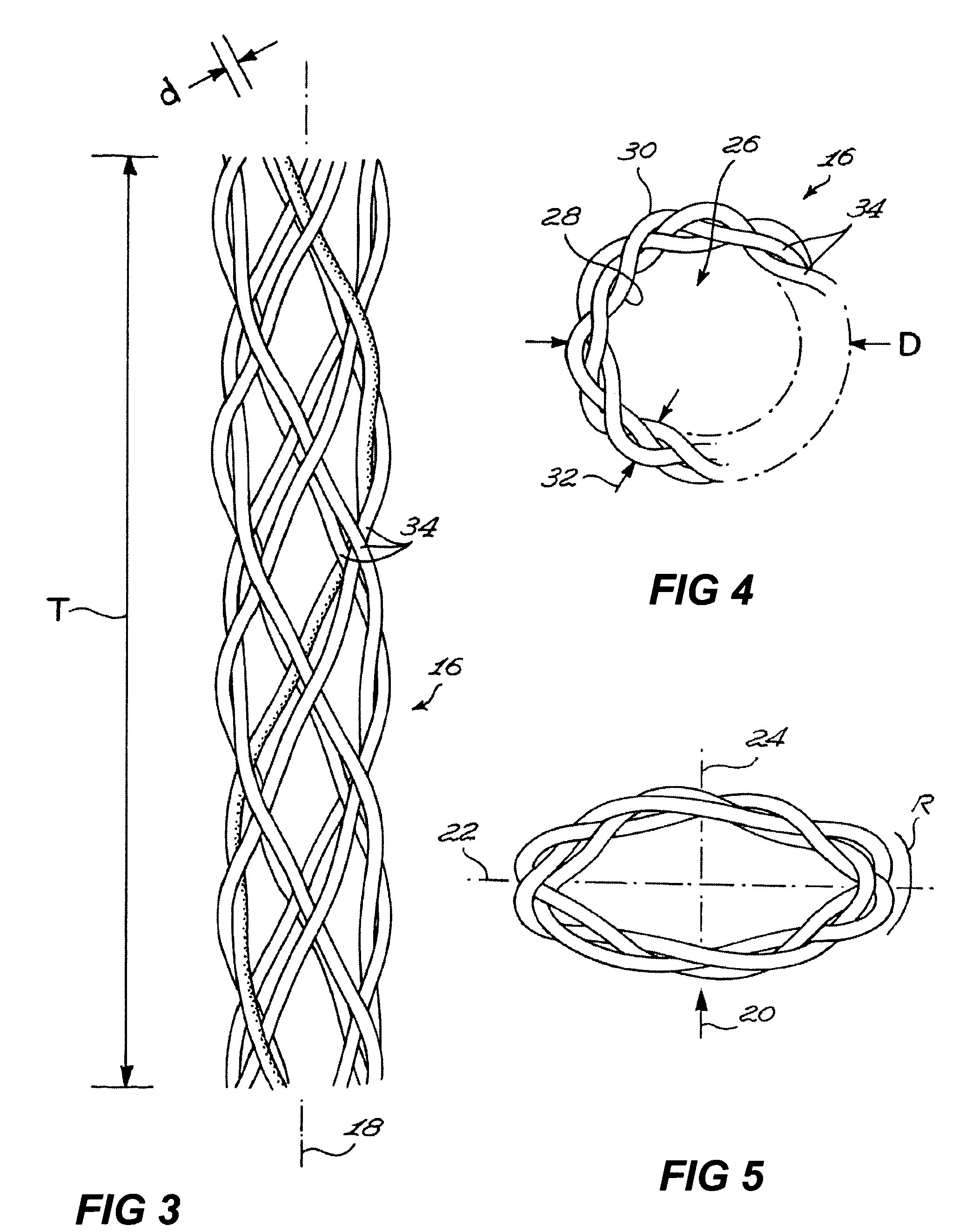
[0108]When used in the context of suturing and, in particular, of suturing or binding together sternal halves, the body 16 preferably has a substantially uniform moment of inertia of bending in all directions so as to facilitate ergonomical manipulation during the various steps leading to sternal closure. In the context of use as sutures and, in particular, sutures for sternal halves, the body 16 is preferably provided with a relatively low moment of inertia of bending. This relatively low moment of inertia of bending is adapted to facilitate manipulation of the binding component 10 and to increase the fit between the binding component 10 and body parts when in contact with each other.
[0109]In order to provide a relatively low moment of inertia of bending that is relatively uniform in all directions, the body 16 preferably has a substantially hollow tubular configuration. As shown in FIG. 4, the body 16 preferably has a substantially annular cross-sectional configuration when radially uncompressed.
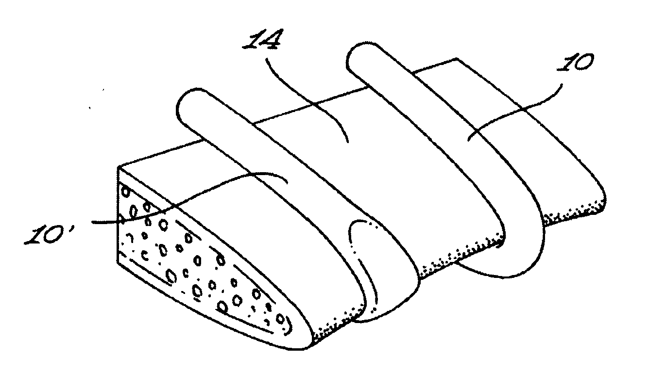
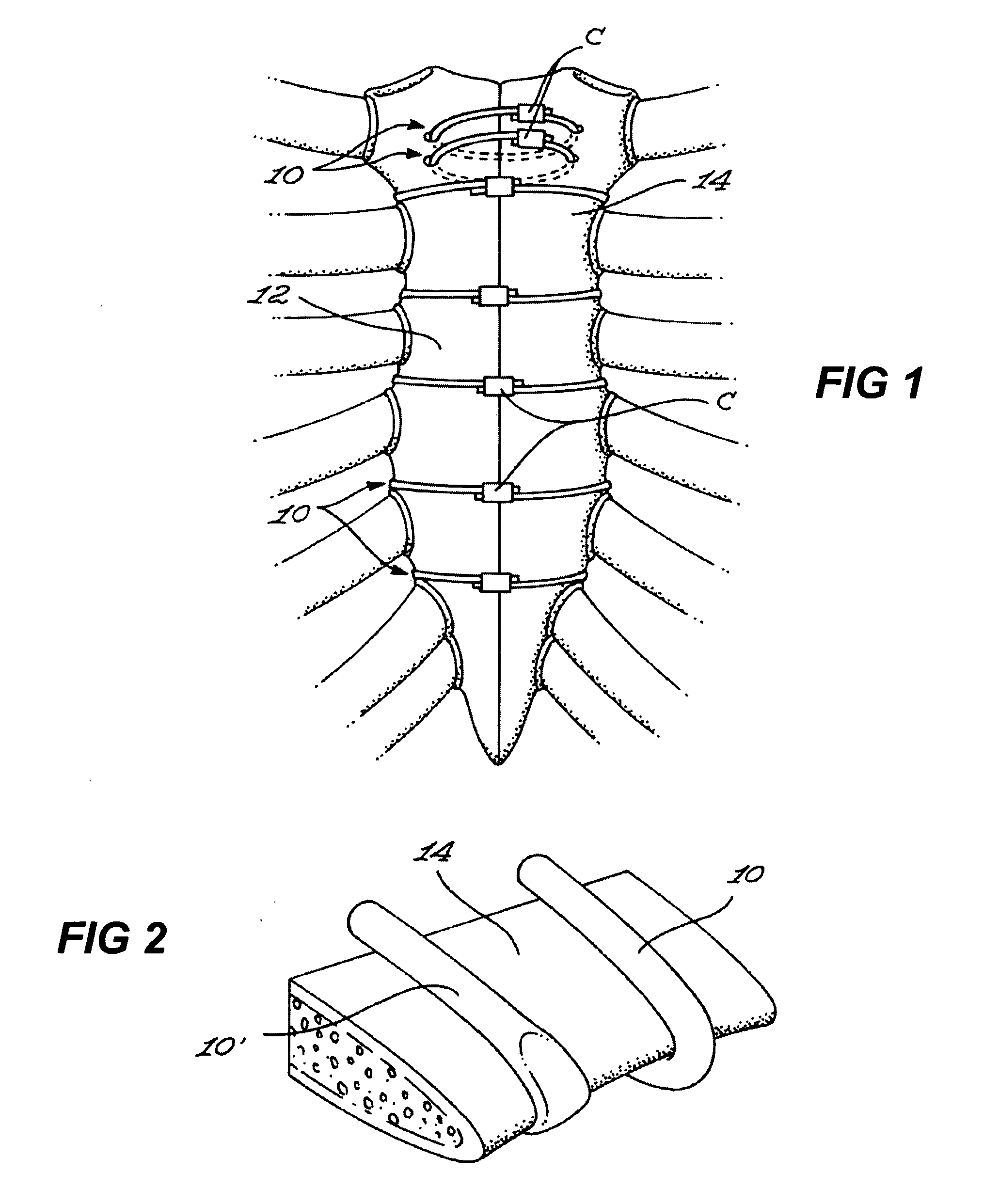
[0111]The propensity of the body 16 to substantially flatten upon application thereon of a radial compressive force inherently increases the size of the contact area between the body 16 and corresponding contacting portions of the sternal bone. This, in turn, inherently reduces the strain exerted locally on the sternum for a given axial load in the body 16. In other words, the radial compressibility of the body 16 helps cushion, distribute and reduce the stresses that are inflicted on the sternal bones by the binding component 10.
[0113]It should, however, be understood that the body 16 could assume other cross-sectional configurations when in a radially compressed configuration without departing from the scope of the present invention. However, the body 16 is preferably configured and sized so as to prevent the formation of thin or squared edges or thin-diameter cross-sections when in a radially compressed configuration so as to reduce the risks of injuring the bone or adjacent tissue surfaces.
[0114]The inherent so-called “shape memory” and “superelasticity” associated with shape memory materials are adapted to combine synergistically with the geometrical characteristics of the body 16 to evenly distribute stresses on the bone and minimize the risks of creating potentially sharp edges. Indeed, despite various potential axial loading patterns, the use of shape memory materials ensures that the advantages associated with the preferred body configuration will be retained as the shape memory materials ensure the integrity of the configuration and its compressible characteristics. More specifically, the body 16 is designed so as to demonstrate superelastic properties when subjected to temperatures substantially in the range of expected human body temperatures. Hence, when the body 16 is laterally compressed against a sternal section, it has a tendency to resiliently bias its configuration towards its initial uncompressed configuration. This, in turn, prevents the formation of relatively sharp edges and substantially reduces the risks of kinking or other deteriorative effects.
[0127]It is within the scope of the invention to impregnate the body 16 with or otherwise apply thereto one or more medical surgically useful substances, for example, a substance which accelerates or beneficially modifies the healing process when the suture is applied to a wound or surgical site. The therapeutic agent can be chosen for its osteogenic promoting capability, its capability for promoting wound repair and/or tissue growth, its anti-microbial properties or for any other suitable indication. Anti-microbial agents such as broad-spectrum antibiotics which are solely released into the tissue can be applied in this manner to aid in combating clinical and sub-clinical infections in a surgical or trauma wound site.
[0128]To promote wounds repair and/or tissue growth, one of more biologically active materials known to achieve either or both of these objectives can be applied to the body 16. In the specific context of promoting the fusion of two sternal halves, the body 16 could be designed to release to or around the sternum an osteogenic factor and/or an angiogenic factor. For example, the body 16 could diffuse or otherwise distribute factors such as HGF, VEGF, BMP, PDGF, aFGF, bFGF, TGF alpha, TGF beta, other cytokines or genes.
[0137]The compone...
View moreBenefits of technology
[0055]It is a general object of the present invention to provide such an improved binding structure. In accordance with the present invention, there is hence provided a binding component for binding together a pair of biological tissues, the binding component comprising an elongated...
View moreAbstract
A binding component for binding together a pair of biological tissues. The binding component includes an elongated body defining a body longitudinal axis, the body being made, at least in part, of a shape memory material. The body is configured and sized so as to be both substantially flexible and substantially compressible in a direction substantially perpendicular to said longitudinal axis.
Application Domain
Technology Topic
Image
Examples
- Experimental program(1)
Example
EXAMPLE 1
[0142]As seen from FIG. 7, the superelastic behaviour of the shape memory alloy (SMA) allows a non-zero zero force to be applied to the sternum even though the width of the sternum tends to decrease as a result of the nature of the healing process. This decrease in the width of the sternum is represented by portions A-B-C of the stress-strain relationship illustrated in FIG. 7. In addition, SMA benefit from the dynamic interference phenomenon [9], and manifest significant hardening under external impulses (for example coughing), as seen in the C-D portion of the stress-strain curve illustrated in FIG. 7, thus providing a quasi-constant pressure onto the sternum once a predetermined load has been reached, as seen from the D-E portion of the curve of FIG. 7. This quasi-constant pressure is defined by the height of the upper plateau of the superelastic loop. Once the disruption is over, the force applied by the closure system to the sternum returns to its initial level on the lower plateau, as illustrated in the E-F-C portion of the stress-strain curve.
[0143]Most researchers use the rigidity of a closure system as an optimization parameter: the greater the rigidity, the better the closure system. However, the rigidity of the closure system does not necessarily reflect its capacity to maintain the compression of the sternal halves either during post-operative events (for example coughing, deep breathing, sudden movement, etc.), or after the disruption is over.
[0144]In fact, it has been determined in several studies [4; 10; 11] that the sternum opens before the application of the maximum force that can be supported by the closure system, irrespective of the type of system used. A reason for this resides in the fact that the as the closure system of a given geometry becomes stiffer, a larger part of substantial stresses brought on by post-operative events such as coughing, is transferred to the sternum, and can result in its local depression, and therefore in the sternum opening under applied forces. Once the disruption is over, any permanent depression will result in a loss of compression forces at the interface between the two halves of the sternum, and consequently, in a decrease in the stability of the bond. It should be mentioned that the capacity of closure systems to reapply compression on the sternum after removing the load is not evaluated in all the aforementioned studies.
[0145]In view of the above, the following experiments have been performed. Given that compression, unlike a static fixation, is a dynamic process since it must be maintained during all dimensional redefinitions occurring in two sternum halves to be bonded, two comparison parameters for closure devices have been investigated: (1) the minimum force needed to open the bond (opening force fo), and (2) the compressive force reapplied by the closure system once the external disruption is over (residual force fr). In the context of these experiments, closure systems using braided superelastic tubes and those using conventional steel wires have been compared with the help of two complementary studies, the first being numerical and the other being experimental. A goal of the first study, which does not take into account the geometric differences between the two systems, is to evaluate the capacity of a superelastic material to accommodate a large proportion of the force exerted by the closure system on the sternum as a result of an external disruption. The second study includes the comparative experimental testing of two closure systems under two different modes of loading: single impulse (imitating coughing or sudden movement of the patient) or repeated (deep breathing).
Numerical Study
[0146]Finite elements analysis has been used to evaluate whether SMA allow the maintenance of residual forces greater than conventional materials. The influence of the geometry of the closure system has not been assessed in this portion of the study and the thoracic system (cage and sternum closure suture) has been considerably simplified. The following assumptions have been made:
1) The effect of the external disruption of the sternum is reduced by the simple forces applied at the contact points of the ribs [10].
2) Since the sternum is sufficiently long, all the wires of the closure system support an equal fraction of the force applied to the sternum [4].
3) No bond is considered to be formed between the two halves of the sternum (osteogenesis has not begun).
Description of the Model
[0147]Given its symmetric nature (force and geometry), only one half of the closure system is represented in the model, as seen in FIG. 8. The components of the closure and sternum system have been simulated by a series of springs: the closure system has been represented by a spring in tension, while the sternum has been represented by two springs in compression.
[0148]The replacement of the sternum by two springs in compression representing the core and the surface layer of the sternum models the interaction between the two halves of the sternum as well as that of the sternum with the closure system. The core spring offers resistance in compression—and not in tension—thus reflecting the absence of a bond between the two halves of the sternum. This spring represents the volume of the sternum that does not undergo any permanent deformation, but stores a part of the energy resulting form the installation of the closure system in compression. The surface layer spring accepts plastic deformations, and thus simulates the deterioration of the sternum under the action of the closure system. The external force Fe is applied at the interface between the two springs representing the sternum.
Finite Elements and Corresponding Material Laws
[0149]The finite elements model (FEM) has been built with the help of ANSYS 8.0 software by using three types of elements [12]. The SOLIDE185 finite element has been used to model both superelastic and steel closure systems: to represent the superelastic behaviour of the braided tube, the SMA material law has been applied, while the BISO material law has been used to simulate the bilinear elastoplastic behaviour of the steel wire. A 1D finite element with the BISO material law was representing the surface of the sternum with elastoplastic behaviour, while a LINK10 finite element with a Linear Elastic material law, which provides resistance in compression, but not in tension, has simulated the sternum core.
[0150]The SMA material law (Table 1) parameters have been obtained from tensile testing to up to 8% of strain of a Ti-50.8 at. % Ni wire with a diameter of 0.71 mm. The corresponding stress-strain curve is illustrated in FIG. 9A.
[0151]The BISO material law parameters for steel (Table 2) has been determined from the tensile testing of a No5 Ethicon suture wire (Somerville, N.J., USA) with a diameter of 0.78 mm. The corresponding stress-strain curve is illustrated in FIG. 9B.
[0152]The bone depression of the sternum under the cut-in action of the closing system has been modeled using data obtained with polyurethane sternum simulators (SawBones, Vashon, Wash., USA). Two densities of the sternum simulators represented two limit cases defined by Hale et al. [13]: a polyurethane with a 0.24 g/cm3 density represented a “weak” sternum while a polyurethane with a 0.48 g/cm3 density represented a “strong” sternum.
[0153]The material law parameters for the BISO sternum surface layer, shown in Table 3, were obtained from the indentation testing of a 0.8 mm thick steel plate into a polyurethane block that was 12.5 mm thick and 10 mm wide. The rigidity of the sternum core was set to 20 times that of the surface layer in order to avoid any significant modification of the overall sternum rigidity resulting from the surface layer depression. The half-width of the sternum was fixed at 25 mm, and the thickness of the surface layer was set at 5 mm. It was assumed that the latter completely absorbed the closure system penetration.
Calculation Algorithm
[0154]A non-limiting objective pursued with the numerical model was to compare the opening fo and residual forces fr provided by SMA and steel sternum sutures. It was assumed that the rigidity of the SMA closure system could be varied by modifying its relative stiffness between 0.05 and 0.35, while the relative stiffness of the steel wire remained constant and equal to 1 (the rigidity of the SMA braided closure system is in fact adjustable through the modification of its geometry and number of filaments [14]).
[0155]The initial force applied during the installation of the system was set at Fi=60 N for a 0.24 g/cm3 sternum and at Fi=350 N, for a 0.48 g/cm3 sternum since these values were close to the resistance limits for the penetration of the sternum simulators. The force resulting from external disruption varied between Fe=0 and 150 N for the low-density polyurethane and between Fe=0 and 600 N for the high-density polyurethane.
[0156]The algorithm of the numerical study could be summarized as follows (see Table 4, for numerical values):
(1) Density is selected for the sternum simulator;
(2) Material is chosen for the closure suture; if it is SMA, its relative stiffness is given an initial 0.05 value, and if it is steel, its relative stiffness is set at 1;
(3) Installation force (Fi) is applied to the closure system;
(4) External disruption is simulated by applying an initial external force Fe; if this force causes the opening of the sternum, the opening force f0 is recorded;
(5) External force is removed and residual force fr is recorded;
(6) If fr>0, the external force is incremented and steps (4)-(5) are repeated until fr=0 or maximum external force is allowed.
(7) The cross-sectional area of the SMA suture is incremented and steps (3)-(7) are repeated.
[0157]Table 4 summarizes the Finite Element Model procedure that were investigated.
Results of the Numerical Study
[0158]The results of the numerical study for the 0.24 g/cm3 sternum are summarized in Table 5. As an example, FIG. 10 illustrates that an SMA suture with an equivalent diameter of 0.22 mm maintained a non-zero residual force at the sternum interface (fr≧0) after an external force Fe, which is 60% greater than that supported by a Ø0.78 mm steel wire: 145 N as opposed to 90 N. However, this was at the expense of a larger sternum opening: after an identical external force of 90 N, the SMA suture allowed a sternum opening of 1.1 mm, while the steel suture allowed an opening of 0.8 mm. Also, the minimum sternum opening force fo is approximately 70 N for all sternum closure devices, which is comparable to the experimentally obtained data [4].
[0159]For the 0.48 g/cm3 sternum model, SMA sutures allowed a residual force to be maintained for external forces Fe greater than 600 N, which was more than twice the force of a severe coughing fit [10]). In comparison, the residual force provided by steel sutures became zero after an external force of 400 N.
Experimental Study
[0160]To consider the geometry of the SMA sternum closure system, a series of experimental tests were undertaken.
Description of the Testing Bench
[0161]FIG. 11 shows the outline of the testing bench used. Two identical closure systems (7) were installed simultaneously on polyurethane blocks (2) simulating the sternum. The installation force was applied with the help of two adjustable loading clamps (3). Two LC703-100 load cells (5) (Omega, Stamford, Conn., USA) installed on each extremity of the testing frame (1) allowed the force at the sternum interface to be measured. An Enduratec ELF 3200 tensile testing machine (4) was used to apply external force. LabView 6.0 (National Instruments Corp., Austin, Tex., USA) data acquisition systems registered the real time displacement of the testing machine's piston as well as the forces measured by the load cells.
Components Used
[0162]A comparison was made between two closure devices: (1) Ø0.78 mm No 5 Ethicon steel wire and Ø3 mm SMA braided 12.5 mm pitch tube made of 24 Ø0.1 mm filaments of Ni—Ti—Cr alloy.
[0163]The 25×10×90 mm polyurethane blocks with a density of 0.24 and 0.48 g/cm3 were used to simulate sternum bones. One of the sides of the samples used for a peristernal installation (FIG. 11, right) was rounded to simulate the edge of the sternum, and those used for the transsternal installation (FIG. 11, left) featured 2.4 mm diameter holes pierced 10 mm from the symmetric plane in order to allow the threading of the closure device.
[0164]The force-displacement diagrams of the sternum simulators (indentation testing) and of the two types of sternum sutures (tensile testing) are shown in FIG. 12.
Experimental Procedure
Testing Modalities
[0165]The experiment was planned to allow two closure systems to be compared under different exploitation conditions: severe coughing (single impulse loading) or deep breathing (cyclical loading), in the case of peristernal or transsternal installations, and for two sternum densities (0.24 and 0.48 g/cm3)—as seen in Table 6.
[0166]The Following Two-Step Procedure was Performed:
1. Application of the Installation (Initial) Force Fi
[0167]The initial force Fi applied to the median sternum closure was a function of the density of the polyurethane sternum simulator. The higher the density, the higher the initial force that can be applied. The initial force for the 0.24 g/cm3 sternum was set at the same level as for the numerical study: 60 N (see Table 4). For the 0.48 g/cm3 sternum, it was set at 200 N.
2. Application of the External Force Fe
[0168]The Single impulse loading mode simulated coughing or sudden movement, and consisted in a series of loading-unloading cycles with incrementally increased amplitude. Each cycle took 10 seconds, and a 15-second dwell time at zero force was respected prior to each subsequent cycle. At each cycle, the force was increased by 25 N, up to a maximum value allowed, which was 125 N for the 0.24 g/cm3 sternum and 445 N for the 0.48 g/cm3 sternum (the latter value was limited by the capabilities of the testing machine). The measurement of the residual force fr was performed prior to each force increment.
[0169]Cyclic loading simulated deep breathing and consisted in 500 cycles of a sinusoidal force varied with a 0.5 Hz frequency between 0 and 60 N (0.24 g/cm3 sternum) and 0 and 200 N (0.48 g/cm3 sternum). The measurement of the residual force was completed after the 500th cycle at zero load.
Results
[0170]The StatGraphics software (StatPoint Inc., Herndon, Va.) was used to analyse the results obtained [15]. The outcome variable was the relative residual force R=fr/Fi. FIG. 13 demonstrates that the use of the SMA suture compared to steel suture allows an average gain of 30% in the relative residual force value as compared to using a steel suture. The results for the other statistically significant (p≦0.05) input variables show that the peristernal installation guarantees higher residual forces than the transsternal installation, and that a large single impulse force causes more damage than light repetitive forces. The effect of the sternum model density variation was not significant.
Discussion
[0171]The experimental study allows the combined effect of the superelastic behaviour and of the tubular geometry of the SMA to be taken into account. In the context of this study, a unique 24-filament SMA braided tube with an inside diameter of 3 mm was tested with sternum simulators having two limit densities.
[0172]For the 0.24 g/cm3 sternum, the 24-filament SMA suture was a bit too rigid. It is therefore likely that the increased contact area between the sternum and closure system was mostly responsible for the 30% gain in residual force when compared to a steel suture. For the 0.48 g/cm3 sternum, the 24-filament SMA suture was a bit too compliant. Nevertheless, the advantage of using a superelastic suture led to a similar 30% gain in residual force as compared to a steel suture. In fact, the 24-filament SMA suture would have demonstrated maximum efficiency for an intermediate density 0.32 g/cm3.
[0173]To reduce the risk of sternum breakage, a median sternotomy closure using a superelastic tubular braid was proposed. The numerical model allowed the net benefit of a binding component in the form of an SMA suture to be demonstrated against the performance of a No5 Ethicon steel suture. It was experimentally proven that the SMA suture preserved compression at the sternum interface when an external disruption occurs, at forces 30 to 60% greater than those endured by the No 5 Ethicon suture regardless of the installation technique used (peristernal or trans-sternal), the type of external force applied (single impulse or repetitive), and the sternum density.
[0174]The above suggests a method for selecting a force-displacement characteristic of a binding component and for manufacturing and using the same. This method is illustrated with the help FIG. 14, which shows an example of a suitable stress-strain curve usable for determining parameters of the binding component. The reader skilled in the art will readily appreciate that while the present document illustrates by way of example a method for manufacturing and using a binding component for closing a sternum, similar methods are usable to manufacture devices that bind together any other suitable biological tissues.
[0175]The method includes selecting a predetermined force-displacement relationship for the structures to bind. For example, this force-displacement relationship is a force-displacement corresponding to a “cut-through” test. This force-displacement relationship may be selected from known force-displacement relationships. For example, if the biological tissues to bind are bones, the force-displacement relationship may be obtained experimentally by a cut-through testing of a bone simulator (for example solid polyurethane biomechanical test blocks) by an indenter taking the form of a wire or of a thin-plate shape. In other examples, the force-displacement curves may be modelled from the density, dimensions and types of bones to bind. The density of the bones may be estimated for a given patient through a CT bone scan or any other suitable imaging modality. In another example, a predetermined bone density is assumed.
[0176]It should be noted that it is not necessary to measure a bone density to manufacture a binding component in accordance with the claimed invention. Indeed, various binding components corresponding to various predetermined bone densities may be manufactured. Then, when the binding component is installed, a specific binding component is selected for a specific patient according to a selection criterion. An example of a selection criterion includes selecting a binding component that has been manufactured assuming that a bone density of the bones to bind is about equal to a bone density measured in the patient.
[0177]For a sternum, the bone density is such that the sternum is typically modelled using a solid rigid polyurethane foam having a density of from about 0.24 g/cm3 to about 0.48 g/cm3. The lower end of this range corresponds generally to the sternum of patients suffering from osteoporosis. In some embodiments of the invention, the bone density of the patient is not known. In these cases, the assumption of a low bone density, for example corresponding to a foam having a density of 0.24 g/cm3, may be advantageous to reduce risks of bone fracture.
[0178]The curve identified as (1) sternum in FIG. 14 illustrates an example of a model of a cut-through displacement-force relationship for a sternum. This model assumes a bilinear relationship wherein the sternum deforms linearly for small displacements. Then, after the yield limit of the sternum has been reached, the sternum deforms irreversibly and linearly with displacement with a lower resistance to deformation.
[0179]As mentioned hereinabove, the force exerted on the binding component by the biological tissues to bind typically diminishes after installation of the binding component. Therefore, to preserve compression between biological structures to bind, it is desirable to exert a relatively large force on the biological tissues when installing the binding component. To that effect, the binding component is prestrained at a level corresponding to a predetermined prestrain force. For example, the predetermined prestrain force is from about 80 to about 95% of the yield limit of a sternum. In a specific example of implementation, the predetermined prestrain force is about 90% of the yield limit of the sternum.
[0180]To improve the capability of the suture to support post-operative events, such as the patient coughing, with reduced risks of failure, the minimum suture resistance, or in other words the ultimate tensile strength, to achieve is set at a predetermined level. For example, in the case of a sternum, this predetermined level is set to between about 200N and about 300N, and more specifically to about 250 N, as determined for a severe coughing fit [10].
[0181]Parameters of the binding device that maximize the residual force fr remaining after the post-operative event is finished are determined. For example, the following variables may be varied: number of filaments, pitch, inside diameter, pitch or helix angle and materials included in the binding device, among others. More details regarding these parameters are found in reference [14]. This maximization is performed, for example, through an iterative modelling process. Methods for optimizing material properties and structures are well-known in the art and will therefore not be described in further details herein.
[0182]In some embodiments of the invention, the maximization of the residual force fr is performed assuming that the displacement-force relationship is similar to the relationship illustrated by the parallelogram-shaped hysteresis curve identified as “(4) SMA braid” in FIG. 14. As shown from this Figure, this relationship includes upper and lower substantially linear plateaus substantially parallel to each other that are connected through straight line segments at both ends thereof. In a specific example of implementation, the residual force fr is maximized by selecting the material composition, dimensions, configuration of the binding component or of its body so that the difference in force between the lower plateau of the force-displacement relationship of the binding component and the upper plateau of the force-displacement relationship of the binding component is minimal.
[0183]The maximization of fr may be performed while satisfying the following criterion: the knee point, or inflection point, between the upper plateau of the SMA curve and the elastic slope of a stress-induced martensite phase should be substantially coincident with the point representing the pretension in the binding device during installation.
[0184]All the constraints described hereinabove have, when simultaneously satisfied, a synergetic effect and provide binding components that have unexpected characteristics. However, in some embodiments of the invention, only some of these constraints are satisfied in specific binding components.
[0185]A specific example of a binding component that has been found to be suitable to bind two halves of a sternum includes 24 filaments of a Ni—Ti—Cr alloy wire having a diameter of 0.075 mm. The wires are braided with a pitch of about 12.5 mm to produce a substantially tubular structure having a diameter of about 3 mm. While parameters describing this binding component have been found using the above-described method, the reader skilled in the art will readily appreciate that this method should not be used to limit the scope of the claimed invention in apparatus claims.
[0186]The above-described example also suggests that a difference in force between the lower plateau of the force-displacement relationship of a binding component in accordance with the invention and the upper plateau of the force-displacement relationship of this binding component of from about 10 percent to about 30 percent of the force to which the prestrain corresponds is achievable.
[0187]From the results relating to the 0.24 g/cm3 foam, which models a typical osteoporotic sternum, a suitable value of a prestrain to which the body of the binding component imay be prestrained is a prestrain corresponding to that generated by a force having a magnitude of from about 55-65 N, or of about 60 N. The use of this prestrain is advantageous in binding component for binding osteoporotic sternums as it helps in minimizing the risks of fractures of the sternum by the binding component.
[0188]Although the present invention has been described hereinabove by way of preferred embodiments thereof, it can be modified without departing from the spirit, scope and nature of the subject invention, as defined in the appended claims.
TABLE 1 SMA (ANSYS) material law used to model a superelastic binding component Param. Unit Value Ex MPa 32000 εtrans m/m 0.037 σMs MPa 335 σMf MPa 385 σAs MPa 200 σAf MPa 150
TABLE 2 BISO (ANSYS) material law used to model a N°5 Ethicon steel binding component Param. Unit Value Ex MPa 90000 Etan MPa 425 σy MPa 1600
TABLE 3 BISO material law for the surface layer and Linear Elastic material law (ANSYS), for a modelled sternum core. Surface layer Core Mat law BISO Linear Elastic Param. Unit 0.24* 0.48* 0.24* 0 48* Ex MPa 735 5200 14 700 104 000 Etan MPa 140 1050 σy MPa 67 400 *Polyurethane density (g/cm3)
TABLE 4 Sequence of FEM procedures followed in numerical modelling of a binding component in accordance with an embodiment of the present invention. External force Fe Materials Suture relative range; Sternum density stiffness; increment Suture (g/cm3) Fi (N) increment (N) Steel 0.24 60 1 [0-150]; 5 0.48 350 [0-600]; 20 SMA 0.24 60 [0.05-0.35]; 0.05 [0-150]; 5 0.48 350 [0.5-1.3]; 0.1 [0-600]; 20
TABLE 5 Results of a numerical model modelling the interaction of a binding device with a foam model of a sternum having a density of 0.24 g/cm3. External force Suture Equivalent Fe Wire relative diameter corresponding type stiffness (mm) to fr = 0 (N) SMA 0.05 0.16 100 (wire break) 0.10 0.22 145 0.15 0.27 135 0.20 0.32 95 Steel 1.00 0.78 90 (n°5)
TABLE 6 Experimental testing modalities for a closure system. Variable Modalities Closure system Steel suture SMA suture Polyurethane 0.24 g/cm3 0.48 g/cm3 density Threading Transsternal Peristernal Loading Single Cyclic impulse
REFERENCES
[0189] [1] Heart disease and stroke statistics—2005 Update. (2005). Dallas: American Heart Association. [0190] [2] Milton, H. (1987). Mediastinal surgery. Lancet, 1, 872-875. [0191] [3] Robicsek, F., Daugherty, H. K., & Cook, J. W. (1977). The prevention and treatment of sternum separation following open-heart surgery. The Journal of Thoracic and Cardiovascular Surgery, 73(2), 267-268. [0192] [4] Casha, A. R., Gauci, M., Yang, L., Saleh, M., Kay, P. H., & Cooper, G. J. (2001). Fatigue testing median sternotomy closures. European Journal of Cardio-thoracic Surgery, 19(3), 249-253. [0193] [5] Soroff, H. S., Hartman, A. R., Pak, E., Sasvary, D. H., & Pollak, S. B. (1996). Improved sternal closure using steel bands: Early experience with three-year follow-up. Annals of Thoracic Surgery, 61(4), 1172-1176. [0194] [6] Combes, J. M., Carrie, J. M., Soula, P., Tricoire, J. L., & Cerene, A. (1993). Fermeture des sternotomies à l'aide des agrafes de Cotrel. Annales De Chirurgie, 47(2), 179-183. [0195] [7] Sargent, L. A., Seyfer, A. E., Hollinger, J., Hinson, R. M., & Graeber, G. M. (1991). The healing sternum: a comparison of osseous healing with wire versus rigid fixation. The Annals of Thoracic Surgery, 52(3), 490-494. [0196] [8] Losanoff, J. E., Richman, B. W., & Jones, J. W. (2002). Disruption and infection of median sternotomy: a comprehensive review. European Journal of Cardio-Thoracic Surgery, 21(5), 831-839. [0197] [9] Duerig, T., Pelton, A., & Stockel, D. (1997, March). Superelasitic Nitinol for Medical Devices. Medical Plastics and Biomaterial Magazine MPV archive. [0198] [10] Casha, A. R., Yang, L., Kay, P. H., Saleh, M., & Cooper, G. J. (1999). A biomechanical study of median sternotomy closure techniques. European Journal of Cardio-Thoracic Surgery, 15(3), 365-369. [0199] [11] McGregor, W. E., Trumble, D. R., & Magovern, J. A. (1999). Mechanical analysis of midline sternotomy wound closure. The Journal of Thoracic and Cardiovascular Surgery, 117(6), 1144-1145. [0200] [12] ANSYS. (2003). ANSYS (Version 8.0) [Finites elements]. Canonsburg, Pa., US. [0201] [13] Hale, J. E., Anderson, D. D., & Johnson, G. A. (1999, Oct. 21-23). A polyurethane foam model for characterizing suture pull-through properties in bone. Paper presented at the 23rd Annual Meeting of the American Society of Biomechanics, University of Pittsburgh. [0202] [14] Baril, Y. (2004). Design and Modelisation of a Sternum Closure System (in French). Master Thesis, École de technologie supérieure, Montreal. [0203] [15] Montgomery, D.C. (1996). Design and analysis of experiments (4th edition ed.). New York.
Login to view more PUM


Description & Claims & Application Information
We can also present the details of the Description, Claims and Application information to help users get a comprehensive understanding of the technical details of the patent, such as background art, summary of invention, brief description of drawings, description of embodiments, and other original content. On the other hand, users can also determine the specific scope of protection of the technology through the list of claims; as well as understand the changes in the life cycle of the technology with the presentation of the patent timeline. Login to view more.
Login to view more Similar technology patents
LED unit and optical source module having the same
InactiveUS20090129083A1Improve structureAchieve functionVehicle headlampsLighting heating/cooling arrangementsEngineeringLight source
Owner:HYUNDAI MOBIS CO LTD
Photo frame structure
InactiveUS20080016742A1Cost reductionImprove structurePicture framesDomestic mirrorsEngineeringVariable angle
Owner:GREAT SUN TECH CORP
Magnetically enhanced power inductor with self-aligned hard axis magnetic core produced using a damascene process sequence
ActiveUS20090094818A1Improve structureEasy formationSemiconductor/solid-state device detailsEmergency protective circuit arrangementsInductorMagnetic core
Owner:NAT SEMICON CORP
Encapsulated organic electroluminescent display
ActiveUS20050014022A1Improve structureDischarge tube luminescnet screensElectroluminescent light sourcesOrganic electroluminescenceChemistry
Owner:SAMSUNG DISPLAY CO LTD
Seating device with a foldable table
InactiveUS20070216201A1Improved support structureImprove structureDismountable chairsFoldable chairsEngineering
Owner:CRAZY CREEK PRODS
Classification and recommendation of technical efficacy words
- Improve structure
Rotating slide-type mobile communication terminal
ActiveUS20060223596A1Improve structureProtective devices for lightingLight guides detailsLiquid-crystal displayEngineering
Owner:PANTECH CORP
Refrigerator with icemaker
ActiveUS20050061016A1Improve structureConvenient for userLighting and heating apparatusIce productionIcemakerFreezing chamber
Owner:LG ELECTRONICS INC
Connector assembly with strain relief member
ActiveUS20080003881A1Reliable connectionImprove structureRelieving strain on wire connectionElectrically conductive connectionsStrain reliefEngineering
Owner:APPLE INC
Gliding structure for glide-open type mobile phone
Owner:GUIMA SCI & TECH