
Liquid dispensing apparatus based on piezoelectrically driven hollow horn

a hollow horn and liquid dispensing technology, applied in the direction of spray nozzles, movable spraying apparatus, spray nozzles, etc., can solve the problems of liquid breaking up, complicated and delicate design, and may be needed a relatively complicated design, etc., to achieve uniform thickness, simple geometry, and easy manufacturing

Inactive Publication Date: 2008-06-05
THE HONG KONG POLYTECHNIC UNIV
View PDF9 Cites 19 Cited by
  • Summary
  • Abstract
  • Description
  • Claims
  • Application Information

AI Technical Summary

Benefits of technology

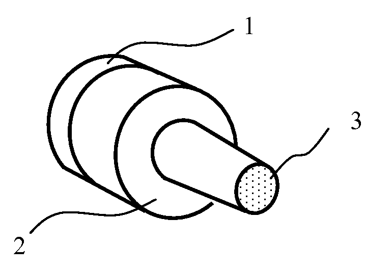
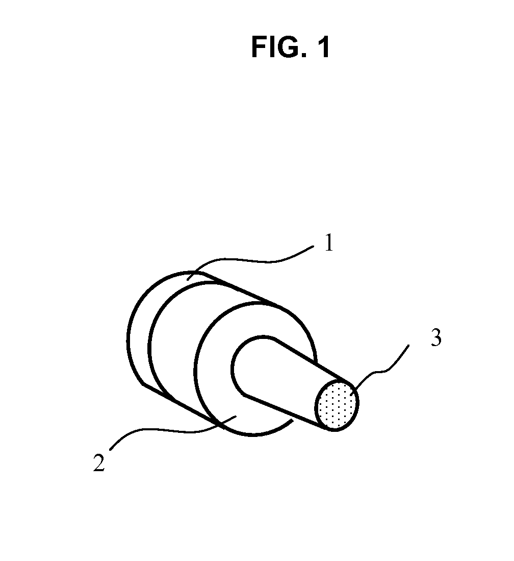
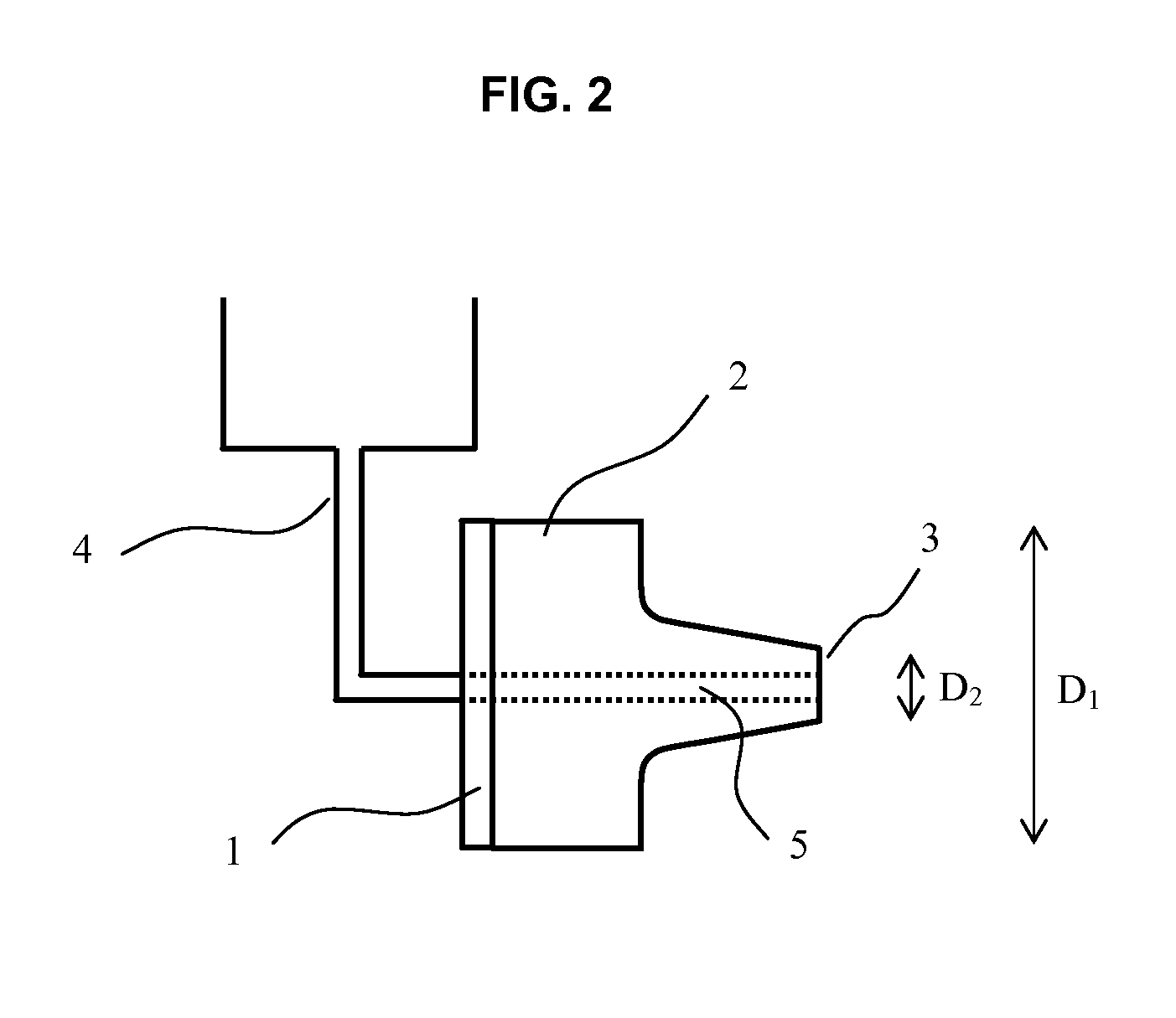
[0011]In this novel design, the mesh is vibrating in piston-like motion at a relatively high frequency (for example, a preferred frequency is 185 kHz). The vibration across the mesh is substantially uniform. The entire vibrating mesh is used for dispensing fine liquid droplets of small size. The mesh has a uniform thickness and simple geometry and thus easier to manufacture. The vibrating mesh is attached on a hollow step-horn, not directly on an oscillator. Because the liquid to be dispensed is not supported by the mesh itself, the resonance vibration of the mesh, including the frequency and amplitude, is not significantly affected by the liquid, which in this novel design is delivered to and contained in the cylindrical cavity before forming fine liquid droplets. The step horn works to amplify the vibration at the mesh and therefore does not rely on a more complex design of the mesh (e.g., a non-uniform cross-section profile and a flexing mode of vibration).
[0012]As the device of the present invention operates at a high frequency, the vibration amplitude required for dispensing fine liquid droplets is small. In addition, the output rate can be higher and / or the size of the device can be made smaller.
[0013]The device of the present invention does not require a layer of fluid adhered on the mesh screen. Rather, the liquid is easily and conveniently delivered to and contained in the cavity of the step horn, where it is in contact with the rare surface of the screen for dispensing fine liquid droplets. This design avoids the leakage problem and allows the device to operate in any orientation.

Problems solved by technology

The mesh of the screen is much finer than the gas stream resulting in the breaking up of the liquid as it is sheared away from or blown out of the screen mesh.
Hence, complicated and delicate design is necessary.
For example, with this existing device, a relatively complicated design may be needed for enclosing the fluid around the vibrating element such that it is leakage-proof and does not affect the vibration of the vibrating surface.

Method used


Image

  • Liquid dispensing apparatus based on piezoelectrically driven hollow horn
  • Liquid dispensing apparatus based on piezoelectrically driven hollow horn
  • Liquid dispensing apparatus based on piezoelectrically driven hollow horn

Examples


Embodiment Construction

[0031]Reference will now be made in detail to an embodiment of the invention, examples of which are also provided in the following description. Exemplary embodiments of the invention are described in detail, although it will be apparent to those skilled in the relevant art that some features that are not particularly important to an understanding of the invention may not be shown for the sake of clarity.

[0032]Furthermore, it should be understood that the invention is not limited to the precise embodiments described below and that various changes and modifications thereof may be effected by one skilled in the art without departing from the spirit or scope of the invention. For example, elements and / or features of different illustrative embodiments may be combined with each other and / or substituted for each other within the scope of this disclosure and appended claims.

[0033]In addition, improvements and modifications which may become apparent to persons of ordinary skill in the art af...


PUM


Abstract

A liquid dispensing apparatus, including a hollow horn having a central cylindrical cavity and a piezoelectric ring having a central opening. The piezoelectric ring is coupled to the hollow horn such that the central opening is in communication with one end of the central cylindrical cavity. A mesh screen is provided at the other end of the central cylindrical cavity. Liquid is delivered to an inner surface of the mesh screen through the central opening of the piezoelectric ring and the central cylindrical cavity of the hollow horn, and is dispensed from an outer surface of the mesh screen in the form of fine liquid droplets.

Description

FIELD OF THE INVENTION[0001]The present invention relates generally to a liquid dispensing apparatus, and in particular to a liquid dispensing apparatus based on piezoelectrically driven hollow horn for dispensing liquid in the form of fine liquid droplets.BACKGROUND OF THE INVENTION[0002]Liquid dispensers for producing fine liquid droplets or aerosols in industrial and medical applications are known. Nebulizer converts liquids into aerosol particles. It has been widely employed in industrial and medical applications; among which the ink-jet printing and drug delivering for respiratory tract devices have attracted considerable interest.[0003]Some examples of industrial application on ink-jet printing were published in (i) S. Kameyama, H. Fukumoto, T. Kimura and S. Wadaka, Ink mist jet generation using low frequency focused ultrasonic waves and nozzle, Proc. of IEEE Ultra. Symp. 1 (1999) 695-678, (ii) G. Percin, and B. T. Khuri-Yakub, Piezoelectric droplet ejector for ink-jet printin...

Claims


Application Information

Patent Timeline
IPC IPC(8): B05B17/04
CPCB05B17/0623A61M15/0085A61M11/005B05B17/063A61M15/025
Inventor CHAN, HELEN LAI WAXU, WENCHENGLAM, KWOK HOKWOK, KIN WING
Owner THE HONG KONG POLYTECHNIC UNIV
Learn More