System and method for controlling motor using parameter associated with magnetic flux

a technology of magnetic flux and motor, which is applied in the direction of motor/generator/converter stopper, electronic commutator control, dynamo-electric converter control, etc., can solve the problems of difficult motor control, association with motor output, and characteristic curve of motor with respect to armature current not represented as ideally linear curves, so as to achieve the effect of reliably grasping the rotational position of the rotor

Inactive Publication Date: 2008-06-05
DENSO CORP
View PDF5 Cites 142 Cited by
  • Summary
  • Abstract
  • Description
  • Claims
  • Application Information

AI Technical Summary

Benefits of technology

[0070]Another specific object of at least a further aspect of the present invention is to provide sensor-less motor control systems, which are capable of reliably grasping a rotational position of a rotor of a motor even if they have no rotational position sensors (encoders).

Problems solved by technology

However, characteristic curves of a motor with respect to armature current are not represented as ideally linear curves.
This may result various problems associated with the motor output.
One of causes that make the motor control difficult is a nonlinear magnetic property of the soft magnetic steel sheets.
This may cause the motor output to be inaccurately controlled when the armature current lies within a nonlinear region of a characteristic curve of the motor; there is the possibility that control errors occur in the motor-output control routines.
In addition, the control system also cannot meet that the d-axis command current id* and q-axis command current iq* determined by the command current determiner 596 each represent an inaccurate value due to the nonlinearity of the magnetic property of the output torque of the motor.
However, when the armature current lies within a nonlinear region of the characteristic curve of the motor, the motor output can be improperly controlled.
Specifically, it may be difficult for the control system to properly control, in the whole region of the motor speed curve or of the motor-output torque curve, the three-phase voltages outputted from the inverter 59G and supplied to the three-phase windings of the motor.
However, when high-speed responsibility is required for the motor control and / or a motor is controlled to be rapidly rotated, the range of the three-phase voltages output from the inverter 59G that can be compensated by the feedback control set forth above is limited.
This may not meet the need of the high-speed responsibility of the motor and also may not meet the rapid rotation of the motor.
This may cause the motor control to become complicated.
In the various types of sensorless motor control, however, because no encoder (rotational position sensor) is provided therein, it may be difficult to properly grasp the rotational position of the rotor.

Method used


Image

  • System and method for controlling motor using parameter associated with magnetic flux
  • System and method for controlling motor using parameter associated with magnetic flux
  • System and method for controlling motor using parameter associated with magnetic flux

Examples


first embodiment

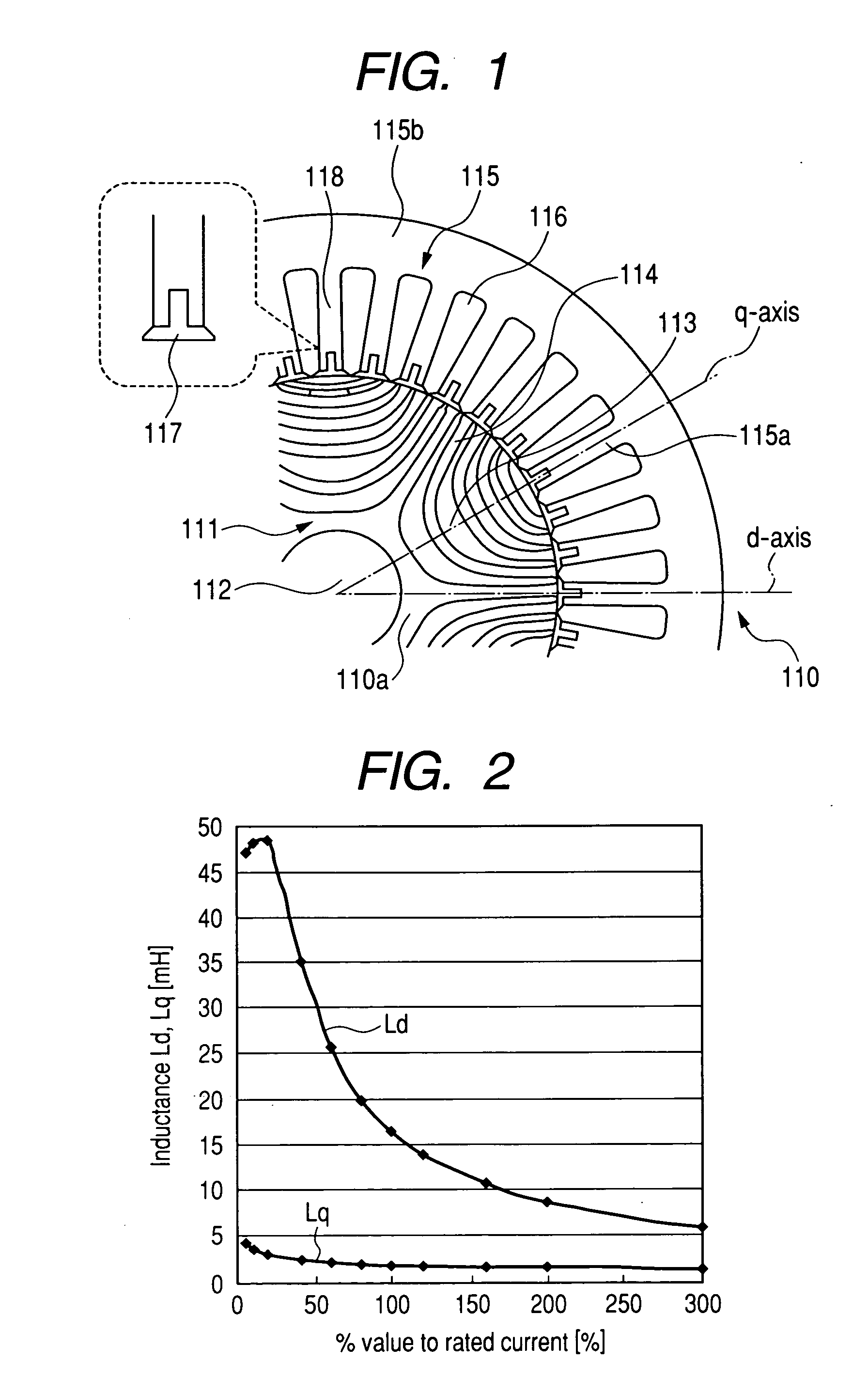
[0143]Referring to the drawings, in which like reference characters refer to like parts in several figures, particularly to FIG. 1, there is illustrated a three-phase and 36-slot synchronous reluctance motor, referred to simply as “motor”110 with six poles.

[0144]The motor 110 is provided with a salient rotor 111 defined as a multi flux-barrier rotor.

[0145]Specifically, the rotor 111 consists of a substantially annular shaped rotor core 111a, a rotor shaft 112 fixed to the inner periphery of the rotor core 111a, and a plurality of groups of flux barriers (slits) 113 formed in the rotor core 111a.

[0146]The rotor core 111a has an external diameter of, for example, 100 mm, and comprises a plurality of magnetic steel sheets and a plurality of non-magnetic stainless sheets each of which has a substantially same annular shape. The magnetic steel sheets and the stainless sheets are so laminated in their axial directions in one stainless sheet in every twenty magnetic steel sheets as to be ...

second embodiment

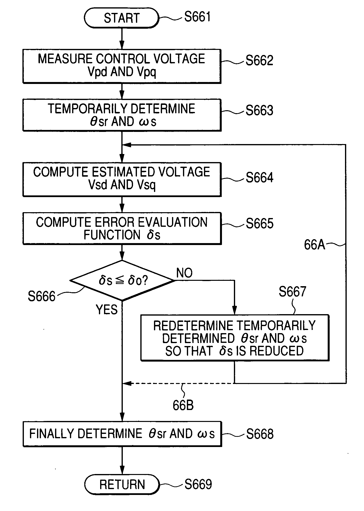
[0694]Next, how to apply the present invention to sensorless (encoder-less) motor control for sensorlessly detect the rotational position of the rotor and the angular velocity thereof will be described hereinafter as a second embodiment of the present invention. Like elements (blocks) between the control system CS and a control system CS1 illustrated in FIG. 28, to which like reference characters are assigned, are omitted or simplified in description.

[0695]In recent years, in order to reduce motor control systems in manufacturing cost and improve the reliability thereof, various types of sensorless (encoder-less) motor control have been widely used. As well as the first embodiment, in the second embodiment of the present invention, proper state parameters representing the behavior of a target motor have been generated to be stored in the data tables T1 and T2 of the control system CS1. Specifically, the control system CS1 is configured to detect the rotational position of the rotor ...


PUM


Abstract

A control method for a motor that rotates based on flux linkages to a winding member of the motor when the winding member is energized by a drive current is provided. The method includes storing magnetic-state information indicative of a relationship between each of a plurality of predetermined operating points of the drive current and a magnetic-state parameter associated with the flux linkages. The method includes obtaining at least one of command information associated with an operating state of the motor and detection information associated with the operating state of the motor. The method includes referencing the magnetic-state information with the use of the obtained at least one of the command information and detection information to obtain a value of the magnetic-state parameter based on a result of the reference. The method includes controlling an output of the motor based on the obtained value of the magnetic-state parameter.

Description

CROSS REFERENCE TO RELATED APPLICATIONS[0001]This application is based on Japanese Patent Application No. 2006-324077 filed on Nov. 30, 2006. This application claims the benefit of priority from the Japanese Patent Applications, so that the descriptions of which are all incorporated herein by reference.FIELD OF THE INVENTION[0002]The present invention relates to systems and methods for controlling various types of motors.BACKGROUND OF THE INVENTION[0003]Motors whose each phase coil is wound around stator poles in full pitch and distributed winding have been widely known. FIG. 34 is a partially axial cross section schematically illustrating an example of the structure of such a conventional motor.[0004]In FIG. 34, the conventional motor is provided with a substantially annular shaped stator core 4, a motor housing 6 in which the stator core 4 is installed, and a pair of coil end portions 5 of stator windings installed in the stator core 4. The motor is also provided with a substantia...

Claims


Application Information

Patent Timeline
Patent Type & Authority Applications(United States)
IPC IPC(8): H02P6/08H02P6/06H02P6/17H02P6/28H02P21/00H02P21/06H02P21/08H02P21/09H02P21/10H02P21/12H02P21/13H02P21/14H02P21/18H02P21/22H02P21/24H02P21/28H02P21/30H02P23/12H02P23/14H02P23/16H02P25/026H02P25/08H02P27/04H02P27/08H02P29/40
CPCH02K1/145H02K1/246H02K3/28H02P6/08H02P6/18H02P21/0039H02P2207/05H02P21/06H02P21/14H02P25/08H02P27/06H02P2203/09H02P21/0042H02P21/24H02P21/26H02P6/10
Inventor NASHIKI, MASAYUKI
Owner DENSO CORP
Why Eureka
Try Eureka