RFID tag and antenna

Active Publication Date: 2008-06-05
THE HONG KONG UNIV OF SCI & TECH
View PDF11 Cites 64 Cited by
  • Summary
  • Abstract
  • Description
  • Claims
  • Application Information

AI Technical Summary

Benefits of technology

[0015]The antenna may perform best when the angle of phase reflection is within a certain range, for example 40° to 115° and −95° to −145°. The precise r

Problems solved by technology

In fact, a radio frequency (RFID) tag with a dipole type antenna may not work when it is attached to a conductive obj

Method used


Image

  • RFID tag and antenna
  • RFID tag and antenna
  • RFID tag and antenna

Examples


Embodiment Construction

[0041]The present invention is useful for radio frequency identification (“RFID”) tags and their antenna systems and can be attached on conductive objects to communicate information with an RFID reader. The RFID tag may be either an active tag which has an internal power source, or a passive tag which gets its power from the electromagnetic waves emitted by the RFID reader. RFID has many applications in areas such as item identification and retail management.

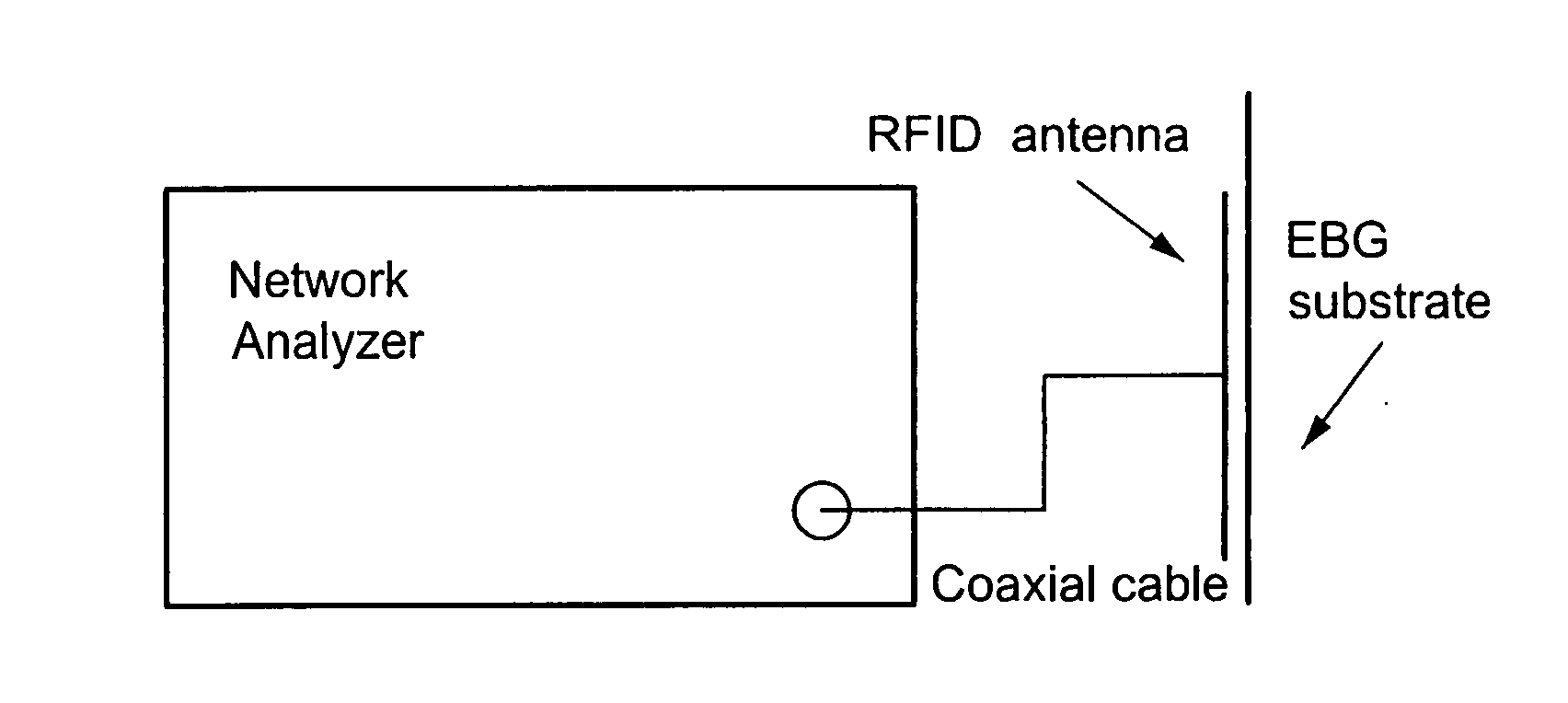
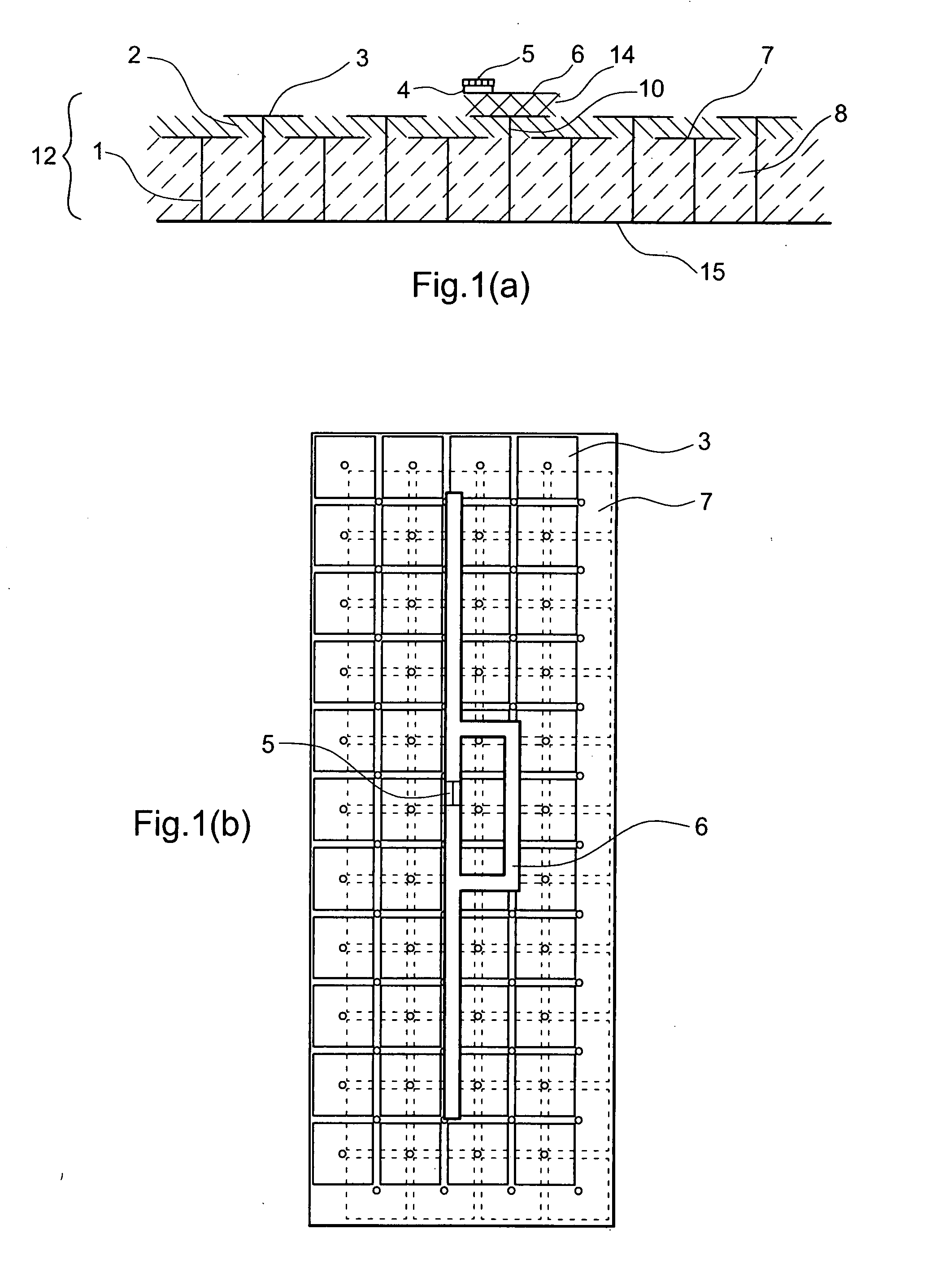
[0042]FIGS. 1(a) and 1(b) show one embodiment of the present invention. An RFID chip 5 is attached to a RFID antenna 6 by anisotropic conductive adhesives (ACAs) 4. The RFID chip may be either active in generating its own power or passive in reflecting energy back to original source (the RFID reader). The RFID chip 5 and antenna 6 are mounted above an electromagnetic band gap substrate 12 with a thin layer of dielectric material 14 between them. In this embodiment, the thickness of dielectric material 14 between the substrate 12...


PUM


Abstract

The present invention relates to an RFID Tag and Antenna for use with an RFID tag and a method of radio frequency identification (RFID). The RFID Tag comprises a RFID chip 5 for storing data, an antenna 6 and an electromagnetic band gap substrate 12. The RFID chip 5 and the antenna 6 are mounted above the electromagnetic band gap substrate 12. The electromagnetic band gap substrate has a reflection phase which is different from 180° at the operation frequency of the antenna. The electromagnetic band gap substrate enables the RFID to operate even if it is mounted on a conductive object, as the reflection phase is not 180° so it does not destructively interfere with the radiation from the antenna at the operating frequency. Preferably the reflection phase is between 340° and 115° or −95° and 145°. The preferred embodiment uses a band gap substrate having two mushroom-like conductive layers 3, 7 with a dielectric in between.

Description

1. FIELD OF THE INVENTION[0001]The invention relates to a RFID tag, an antenna for use with an RFID tag and a method of radio frequency identification (RFID). Preferred embodiments use an electromagnetic band gap. Preferred embodiments use a dipole antenna.2. DESCRIPTION OF PRIOR ART[0002]Radio frequency identification (RFID) is used in a number of applications in which a RFID tag is attached to objects. The RFID tag has an antenna, usually of the dipole type. The antenna is typically arranged for transmitting or receiving ultra high frequency (UHF) signals and the RFID tag may receive both power and data from a data reader's antenna, which communicates with the antenna of the RFID tag. Generally, a RFID antenna is designed for a specific or a narrow range of objects tracking. The radio frequency identification (RFID) tag is attached to objects which are to be tracked. The electromagnetic properties of the objects can affect the impedance, bandwidth and radiation efficiency of the r...

Claims


Application Information

Patent Timeline
IPC IPC(8): G08B13/14
CPCG06K19/07749H01Q15/008H01Q1/2216
Inventor YUEN, MATTHEW MING FAIGAO, BOMURCH, ROSS DAVIDCHENG, CHI HO
Owner THE HONG KONG UNIV OF SCI & TECH
Why Eureka
Try Eureka