Thermoelectric Conversion Module, Heat Exchanger Using Same, and Thermoelectric Power Generating Apparatus

a technology of conversion module and heat exchanger, which is applied in the direction of electrical apparatus, thermoelectric device details, and junction materials of thermoelectric devices, etc., can solve the problems of not being able to meet the heat resistance of soldering described in patent references 1 and 2, and the thermoelectric element of a power generating system used for a waste heat boiler cannot be used, etc., to achieve the effect of improving reliability, improving reliability, and improving practicability as a modul

Inactive Publication Date: 2008-06-12
KK TOSHIBA +1
View PDF14 Cites 39 Cited by
  • Summary
  • Abstract
  • Description
  • Claims
  • Application Information

AI Technical Summary

Benefits of technology

[0012]An object of the invention is to provide a thermoelectric conversion module of which practical utility as a module is enhanced by improving reliability, electrical conductivity, thermal conductance and the

Problems solved by technology

Resource depletion is expected, and it is a very significant issue to consider how energy is used effectively, and various types of systems have been proposed.
The above-described Bi—Te based thermoelectric semiconductors have a usable temperature of up to 200° C. and are effective for cooling devices and the like using the Peltier effect but cannot be used for the thermoelectric element of a power generating system used for a waste heat boiler or the like.
However, for example, soldering described in Patent References 1 and 2 cannot satisfy the hea

Method used


Image

  • Thermoelectric Conversion Module, Heat Exchanger Using Same, and Thermoelectric Power Generating Apparatus
  • Thermoelectric Conversion Module, Heat Exchanger Using Same, and Thermoelectric Power Generating Apparatus
  • Thermoelectric Conversion Module, Heat Exchanger Using Same, and Thermoelectric Power Generating Apparatus

Examples


example 1

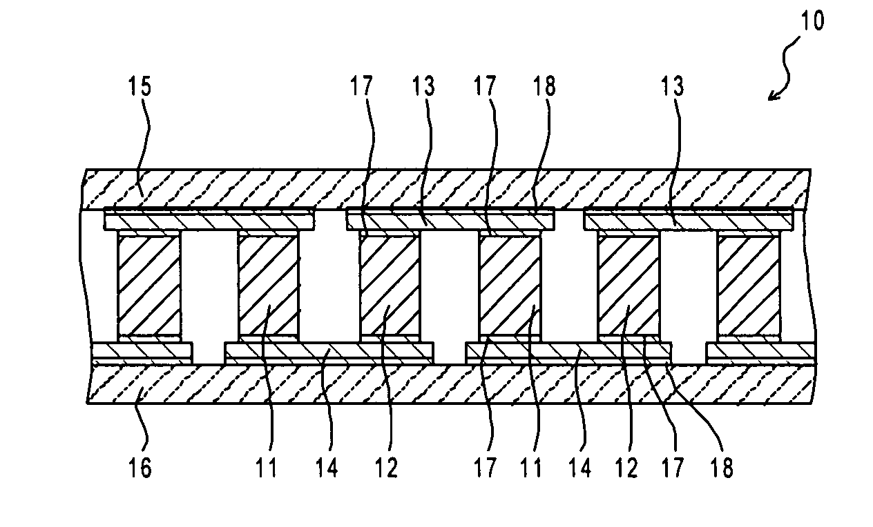
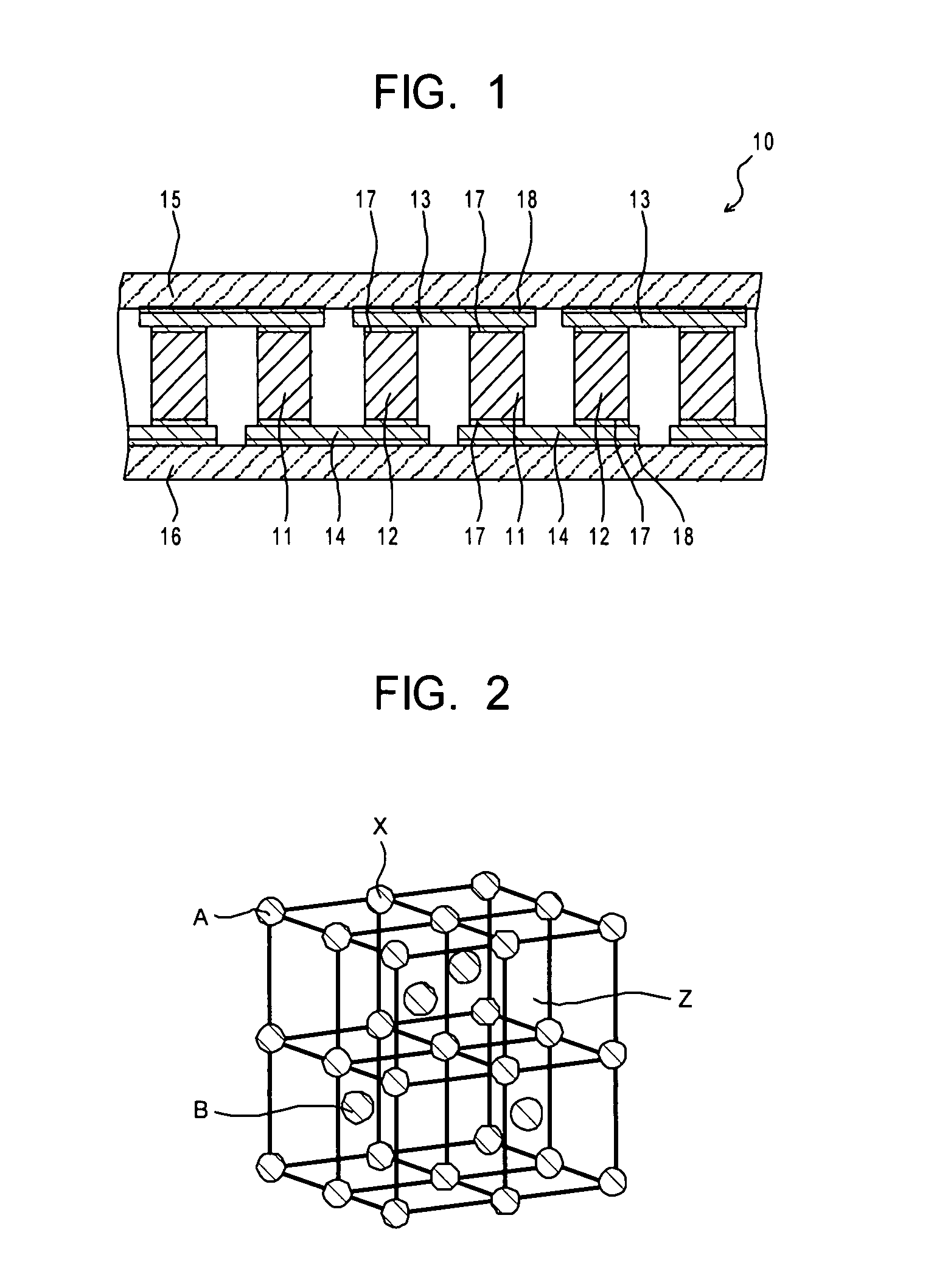
[0073]The thermoelectric conversion module shown in FIG. 1 was produced by the following procedure. First, a thermoelectric element production example will be described.

[0074](n-Type Thermoelectric Element)

First, Ti, Zr, Ni and Sn were weighed and mixed so to have a (Ti0.5Zr0.5) NiSn composition. The mixture raw material was charged into a copper hearth being cooled with water within an arc furnace and arc melted in a decompressed Ar atmosphere. The alloy was pulverized with a mortar and subjected to pressure sintering under conditions of an Ar atmosphere of 80 MPa at 1200° C. for one hour to obtain a disk-shaped sintered body having a diameter of 20 mm. The obtained sintered body was cut into a desired shape to obtain the thermoelectric elements.

[0075](p-Type Thermoelectric Element)

Ti, Zr, Fe, Co and Sb were weighed and mixed to obtain a (Ti0.5Zr0.5) (Fe0.2Co0.8) Sb composition. The mixture raw material was charged into a copper hearth being cooled with water within an arc furnace ...

examples 2 to 9

[0083]The same thermoelectric conversion modules as that of Example 1 were produced except that the combinations of the thermoelectric elements, electrodes and bonding materials were changed. The thermoelectric conversion modules were evaluated for their performance in the same manner as in Example 1. Table 1 shows the combinations of the thermoelectric elements, electrodes and bonding materials and the evaluated results of individual modules. In any of the combinations according to Examples 2 to 9, the bonding parts were free from peeling or a crack even after repeating an operation of holding at 500° C. for ten minutes for 30 times or more.

example 35

[0092]The n-type thermoelectric element having a (Ti0.3Zr0.35 Hf0.35)NiSn composition and the p-type thermoelectric element having a (Ti0.3Zr0.35Hf0.35)CoSb0.85Sn0.15 composition were prepared. The bonded surfaces of the individual thermoelectric elements had surface roughness Ra of 4 μm. They were used to produce a thermoelectric conversion module as follows. First, a paste of a Ti-containing Ag—Cu brazing material having a composition ratio (mass ratio) of Ag:Cu:Sn:Ti:C=60.5:23.5:10.0:4.0:2.0 was screen-printed on an Si3N4 plate having a thickness of 0.7 mm. After drying it, Cu electrode plates were arranged in six vertically and in 12 horizontally on the paste layer, and a total of 50 Cu electrode plates were arranged on the Si3N4 plate. Then, a heat treatment was performed in a vacuum of 0.8 Pa or less at 800° C. for 20 minutes to bond the Si3N4 plate and the Cu electrode plates. The above-described brazing material was used to bond the Cu plates to the entire surface opposite t...


PUM


Abstract

A thermoelectric conversion module (10) comprises first and second electrode members (13, 14), and thermoelectric elements (11, 12) arranged between the electrode members (13, 14). The thermoelectric elements (11, 12) are made of a half-Heusler material and are electrically and mechanically connected to the first and second electrode members (13, 14) via bonding parts (17). The bonding parts (17) include a bonding material which contains at least one selected from Ag, Cu and Ni as a main component and at least one of active metal selected from Ti, Zr, Hf, Ta, V and Nb in a range from 1 to 10% by mass.

Description

TECHNICAL FIELD[0001]The present invention relates to a thermoelectric conversion module using a thermoelectric material including as a main phase an intermetallic compound having an MgAgAs crystalline structure, a heat exchanger using it, and a thermoelectric power generating apparatus.BACKGROUND ART[0002]Resource depletion is expected, and it is a very significant issue to consider how energy is used effectively, and various types of systems have been proposed. Among them, a thermoelectric element is expected as a device which recovers energy which has been abandoned uselessly into the environment as exhaust heat. The thermoelectric element is used as a thermoelectric conversion module which has p-type thermoelectric elements (p-type thermoelectric semiconductors) and n-type thermoelectric elements (n-type thermoelectric semiconductors) alternately connected in series.[0003]For example, a conventional waste heat boiler is designed in order to merely obtain steam or hot water by pa...

Claims


Application Information

Patent Timeline
IPC IPC(8): H01L35/02
CPCH01L35/08H10N10/817H10N10/851H10N10/13
Inventor HIRONO, SHINSUKENABA, TAKAYUKIOKAMURA, MASAMI
Owner KK TOSHIBA
Why Eureka
Try Eureka