Systems and Methods for Laser Bonding Catheter Components

a technology of laser bonding and catheter components, applied in the field of medical devices, can solve the problems of limiting the types and varieties of materials, adding undesirable costs to the construction of medical devices, and difficult to remove shrink tubing from catheter components

Inactive Publication Date: 2008-06-12
CORDIS CORP
View PDF9 Cites 12 Cited by
  • Summary
  • Abstract
  • Description
  • Claims
  • Application Information

AI Technical Summary

Benefits of technology

[0007]Some medical catheters include polymer components that are affixed together. When polymer components are affixed together, the desirable properties of such a joint, seal or bond between components may include its strength, and its ability to hold high fluid pressures or to exhibit high pull strength. It is desirable to provide systems and methods for laser bonding catheter components effectively and efficiently.
[0008]An additional desirable feature of catheter component bonding techniques may include minimizing heating during formation of the bond, so as to minimize any adverse impact on flexibility which may occur during bonding. Another desirable feature may include creating a bond having as small a size as possible.
[0013]It is thus desirable to form a laser bond having the desired features, between any two or more catheter components made of material(s) including at least one polymer, and where the method provides efficient and effective bonding.
[0014]It is also desirable to provide a repeatable source of compression at the desired site of the bond, which is transparent to the laser energy, as well as being easily removable. Another desirable feature is a compression source that is reusable, in other words that does not require a one-time use production item to be discarded each time a laser bond is made.

Problems solved by technology

This requirement of an overlapping common wavelength for high absorption in all of the components to be bonded necessarily limits the types and varieties of materials that can be selected for a particular catheter.
However, a new piece of shrink tubing must be used for each unit, which may add undesirable cost to constructing the medical device.
Also, it may be difficult to remove the shrink tubing from the catheter components after bonding.

Method used


Image

  • Systems and Methods for Laser Bonding Catheter Components
  • Systems and Methods for Laser Bonding Catheter Components
  • Systems and Methods for Laser Bonding Catheter Components

Examples


Embodiment Construction

[0026]The following description of the preferred embodiments of the present invention is merely illustrative in nature, and as such it does not limit in any way the present invention, its application, or uses. Numerous modifications may be made by those skilled in the art without departing from the true spirit and scope of the invention.

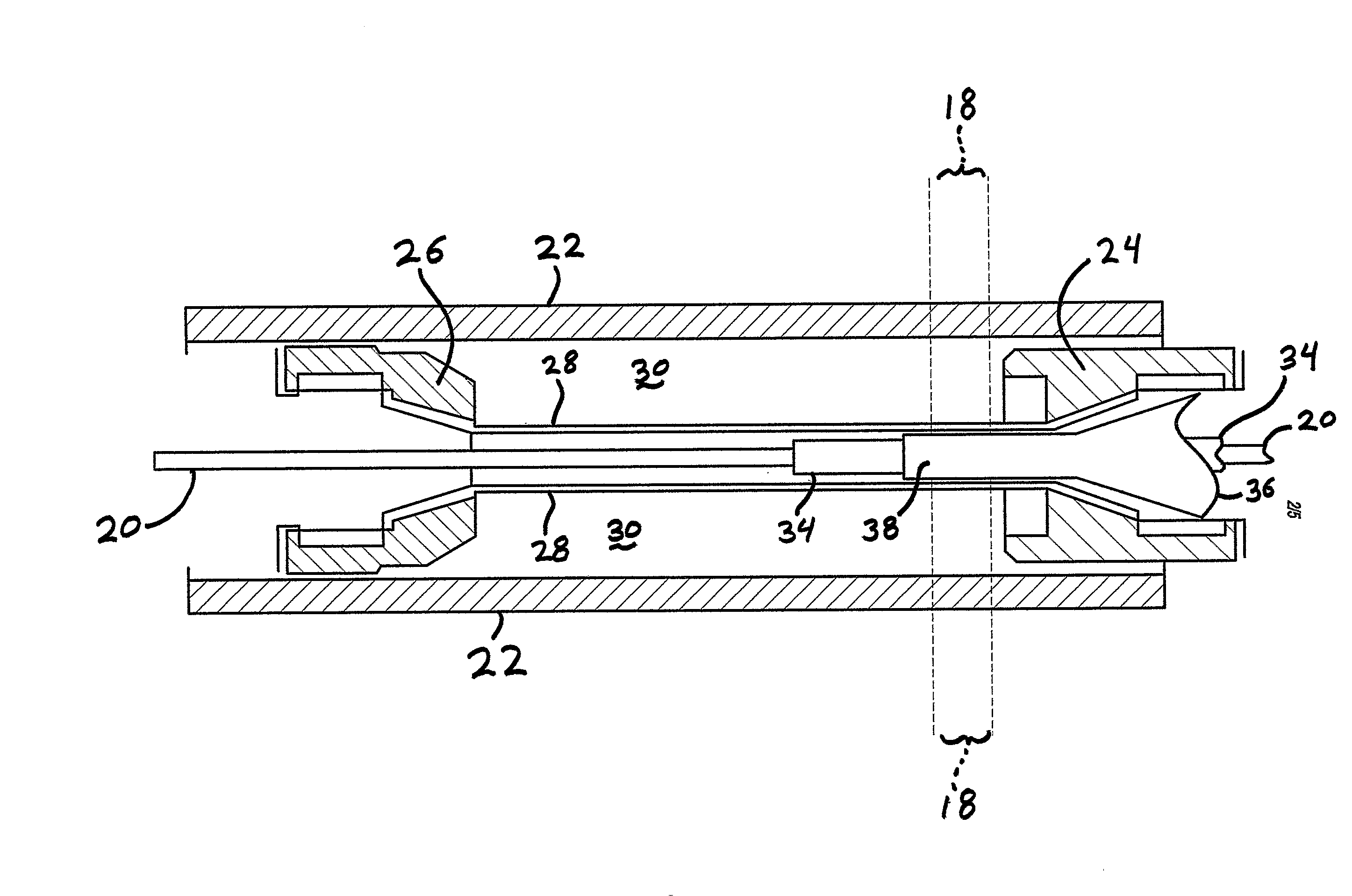
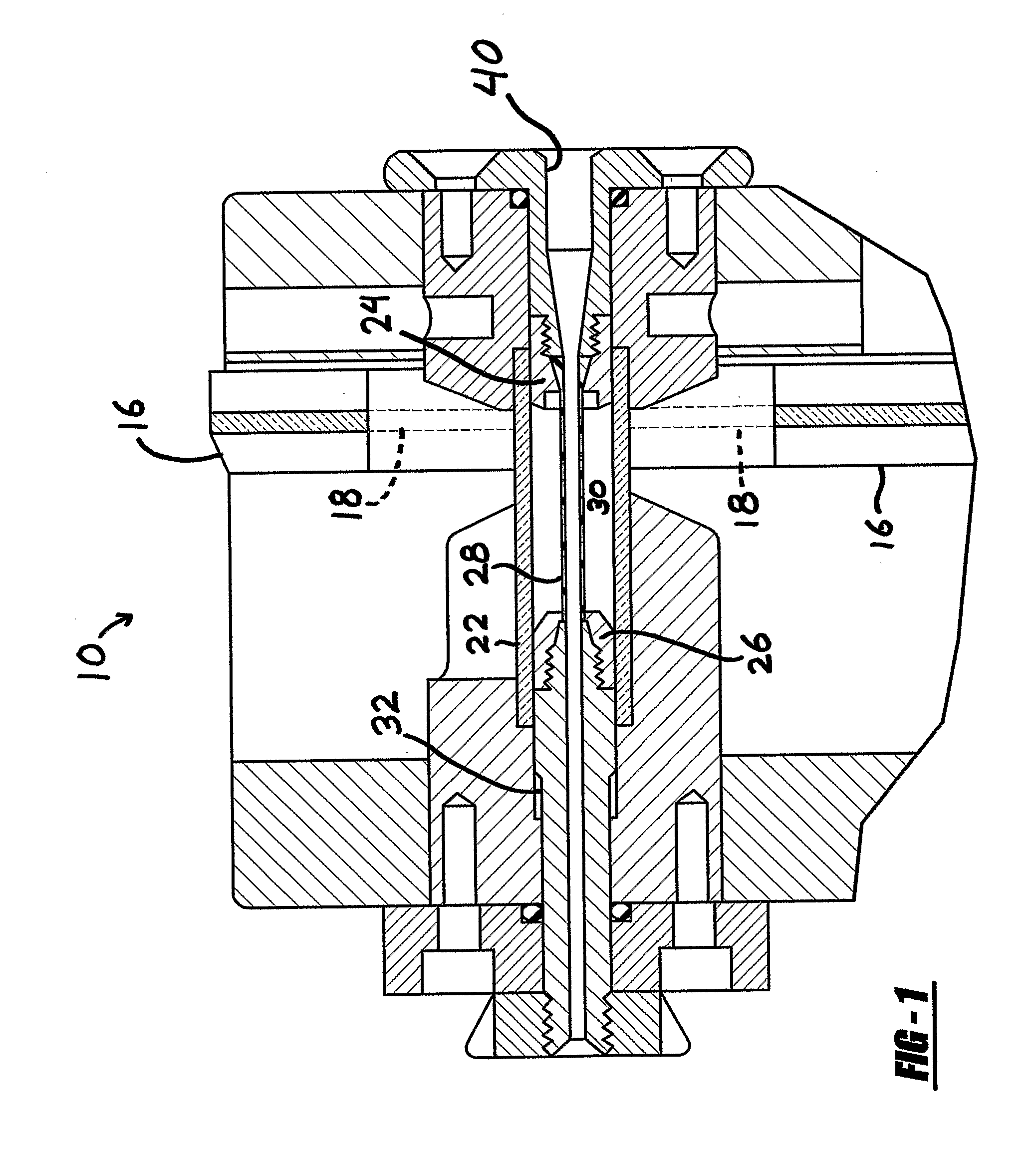
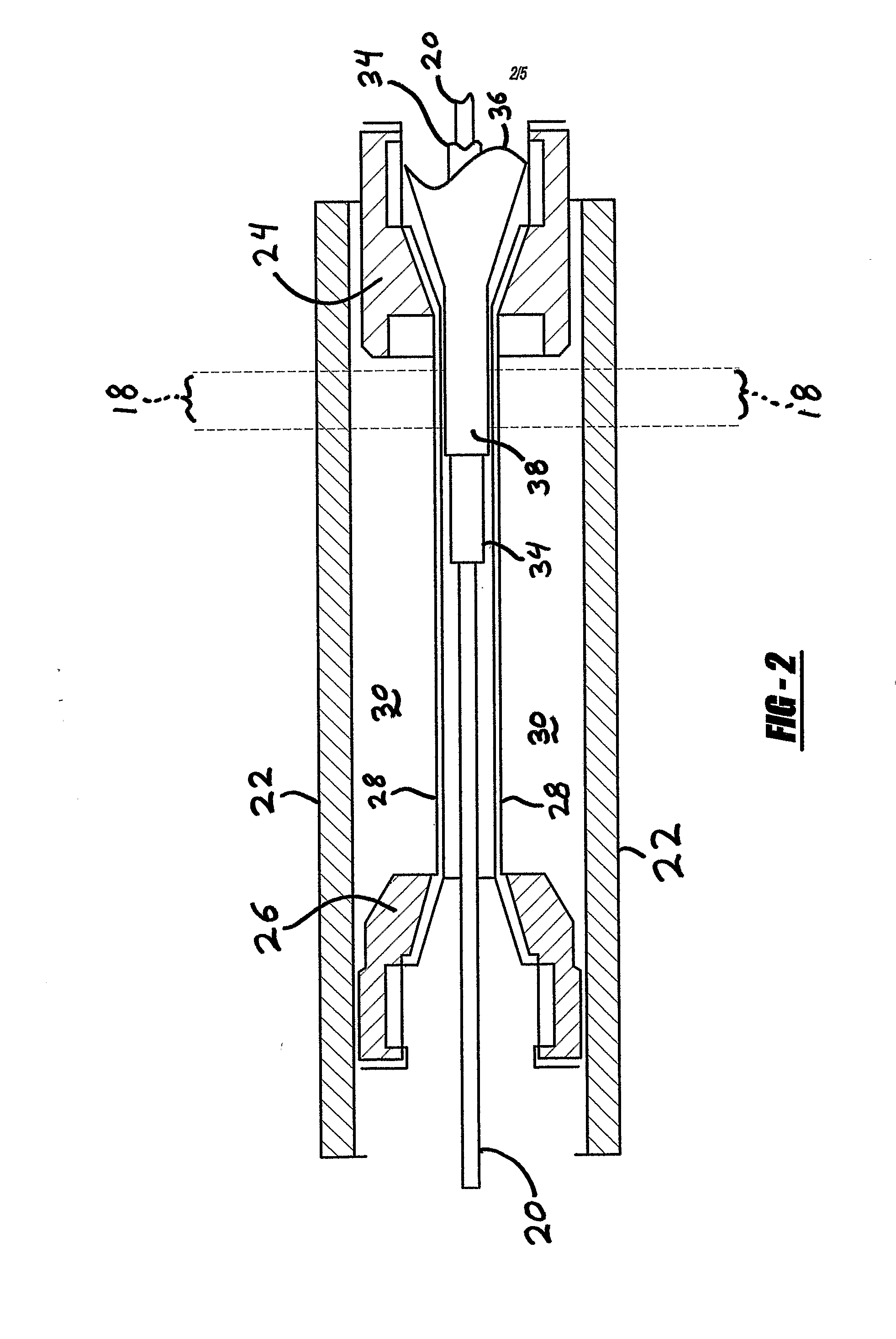
[0027]According to one example of the present invention, a system 10 for laser bonding two or more catheter components is depicted in the drawings. The system 10 includes a laser generator 12, an optical fiber 14 or other element for transmitting the laser energy, and one or more emitters 16 for emitting the laser energy directed toward the catheter components to be bonded. A laser beam 18 is indicated with dashed lines. The system 10 may also include a mandrel 20 for supporting the catheter components.

[0028]A pressure chamber is defined by a tubular outer wall 22, a first and second end assembly 24 and 26, and a flexible compression tube 28. Togethe...


PUM

PropertyMeasurementUnit
angleaaaaaaaaaa
specific wavelengthaaaaaaaaaa
pressureaaaaaaaaaa

Abstract

Systems and methods are described for laser bonding polymer catheter components by using laser energy to create localized heat fusion bonds between two or more polymer catheter components.

Description

CROSS-REFERENCE TO RELATED APPLICATION[0001]This application claims the benefit of priority of United States Provisional Patent Application No. 60 / 573,588 filed on May 21, 2004.BACKGROUND AND SUMMARY OF THE INVENTION[0002]1. Technical Background[0003]The present invention relates generally to medical devices, and more particularly to laser bonding of medical catheter components.[0004]2. Discussion[0005]Many different medical therapeutic treatments are conducted using catheters and catheter systems of various kinds. Examples of different type of catheter include balloon catheters, diagnostic catheters, guiding catheters, stent delivery system catheters, injection catheters, gene therapy catheters, electrophysiology catheters, therapeutic drug delivery catheters, ultrasound catheters, laser angioplasty catheters, etc.[0006]The components of medical catheters are often made of materials including polymers or plastics. Such polymer materials may be selected to have acceptable properties...

Claims


Application Information

Patent Timeline
Patent Type & Authority Applications(United States)
IPC IPC(8): B29C65/16A61M25/10A61F2/958
CPCA61M25/10B29L2031/7543A61M25/1036B29C65/1635B29C65/1664B29C65/1674B29C65/1683B29C65/1687B29C66/1122B29C66/63B29C66/81267B29C66/81455B29K2023/06B29K2023/065B29K2067/00B29K2071/00B29K2075/00B29K2077/00B29K2883/00B29K2909/08B29K2995/0056B29L2031/7542A61M25/1034B29C66/53241B29C65/1667B29L2022/022B29C66/71B29C66/73921B29C66/8122B29K2995/0027
Inventor HE, FUGUISIDWELL, SCOTT B.TROTTA, THOMAS N.
Owner CORDIS CORP
Why Eureka
Try Eureka