
Spherical Aberration Corrected Electrostatic Lens, Input Lens, Electron Spectrometer, Photoemission Electron Microscope And Measuring System

an electrostatic lens and spherical aberration technology, applied in the direction of instruments, heat measurement, material analysis using wave/particle radiation, etc., can solve the problems of general electrostatic lens inability to focus, insufficient acceptance angle of about 30° or less for structural analysis, and inability to achieve spherical aberration. , to achieve the effect of wide acceptance angl

Inactive Publication Date: 2008-06-12
NARA INSTITUTE OF SCIENCE AND TECHNOLOGY +1
View PDF4 Cites 9 Cited by
  • Summary
  • Abstract
  • Description
  • Claims
  • Application Information

AI Technical Summary

Benefits of technology

[0013]According to the spherical aberration corrected electrostatic lens of the present invention, the spherical aberration is corrected by using non-spherical mesh. In this way, an acceptance angle of±60° is realized. Sensitivity of a lens is proportional to square of the acceptance angle. Therefore, dramatic improvement in sensitivity and performance is expected in using this lens as a first stage of an input lens of an electron spectrometer system.

Problems solved by technology

However, a general electrostatic lens cannot focus, into one point, beams within a wide opening angle due to spherical aberration.
However, the acceptance angle of about 30° or less is insufficient for performing the structural analysis of atomic arrangements.
Furthermore, it has been proved that spherical aberration inevitably occurs in an electron lens, and that zero spherical aberration cannot be attained in a general lens configuration, in which a special electric charge in axial symmetry is not present.
This prevents realization of a large acceptance angle.
However, it is difficult to set the energy of the electrons high in electron spectrometers which are used for measuring electrons having an energy of several keV at most.
Moreover, there is such a problem that it is difficult to shape the foil to have a curved surface, because, even if the electrons have a high energy, the foil should be sufficiently thin in order to prevent scattering of the electrons and the absorption of the electrons.
Note that up to third order spherical aberration can be reduced to zero with a flat foil but it is difficult for the flat foil to cancel out higher order spherical aberration.
However, the foil is not an effective means for correcting the spherical aberration for the beams within an opening angle of several tens degrees, which is required in electron spectrometers.

Method used


Image

  • Spherical Aberration Corrected Electrostatic Lens, Input Lens, Electron Spectrometer, Photoemission Electron Microscope And Measuring  System
  • Spherical Aberration Corrected Electrostatic Lens, Input Lens, Electron Spectrometer, Photoemission Electron Microscope And Measuring  System
  • Spherical Aberration Corrected Electrostatic Lens, Input Lens, Electron Spectrometer, Photoemission Electron Microscope And Measuring  System

Examples


Embodiment Construction

[0023][1. Spherical Aberration Corrected Electrostatic Lens according to the Present Invention]

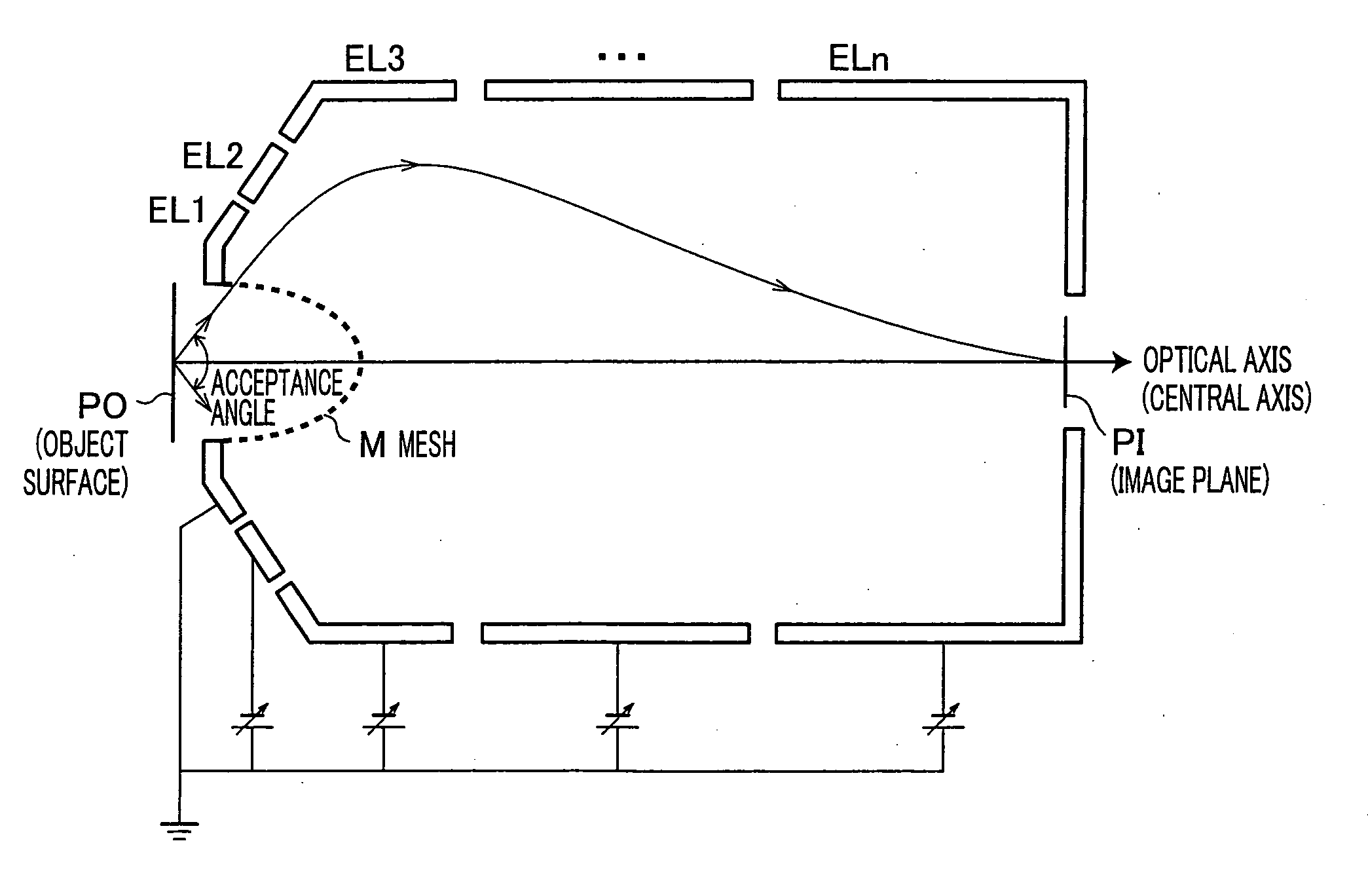
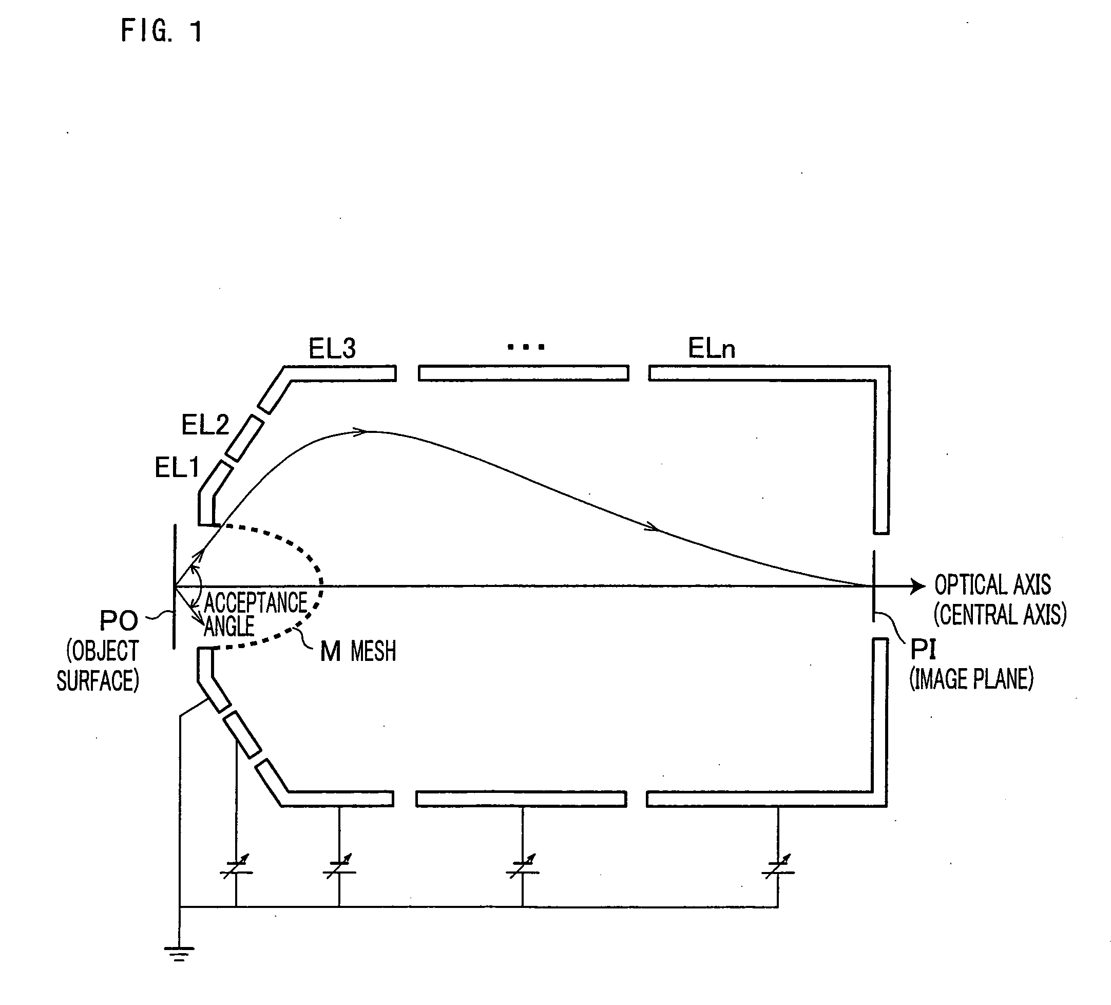
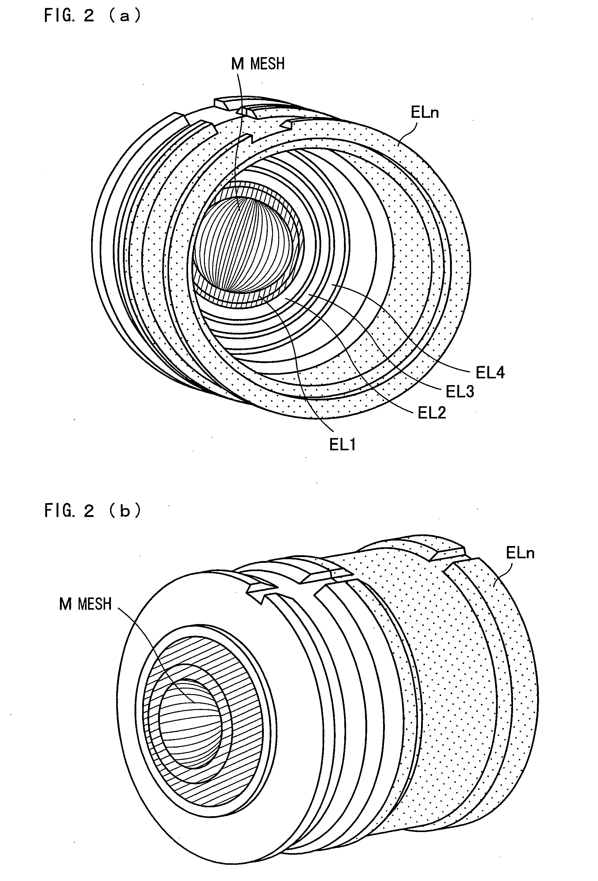
[0024]In FIG. 1, an embodiment of the spherical aberration corrected electrostatic lens according to the present invention is illustrated. The lens is provided with a mesh M, a plurality of electrodes EL1 to ELn, and a power source (not shown). The mesh M has an ellipsoid shape or a shape close to the ellipsoid shape, and is axially symmetric about an optical axis. The mesh M, which is concave toward an object plane, is so as to form a magnified virtual image having a negative spherical aberration, for electron beams or ion beams emitted within a certain opening angle from a predetermined position of the object plane. The plurality of electrodes EL1 to ELn, which have concentric surfaces, form a convergent electric field that form a real image from the magnified virtual image and generate a positive spherical aberration. The power source is used for respectively applying arbitrary voltages...


PUM


Abstract

A mesh (M) having an ellipsoid shape or a shape close to the ellipsoid shape is attached to an electrode (EL1) among electrodes (EL1 to ELn). Voltages of the later-stage electrodes (EL2 to ELn) are appropriately set. With this arrangement, a local negative spherical aberration generated by the mesh (M) is cancelled out with a positive spherical aberration. This optimizes an electric field distribution. As a result, this realizes an electrostatic lens whose acceptance angle is extended to about±60°.

Description

TECHNICAL FIELD [0001]The present invention relates to a first-stage input lens for use in electron spectrometers such as XPS (X-ray Photoelectron Spectrometer), and AES (Auger Electron Spectrometer), and the like, and in PEEM (Photoemission Electron Emission Microscope). BACKGROUND ART[0002]In many conventional electron spectrometers, an electrostatic lens called as an input lens is used in an electron acceptance section of energy analyzer (typically, electrostatic semi-spherical analyzer). The input lens has functions of (i) accepting, as many as possible, electrons emitted from a specimen, (ii) decelerating the electron, and (iii) introducing the thus decelerated electron into the analyzer. In this way, the input lens improves energy resolution.[0003]Moreover, some electron spectrometers are provided with a function of limiting a field of view through which the electron is accepted from a surface of the specimen. In the electron spectrometers having such an arrangement, their sen...

Claims


Application Information

Patent Timeline
Patent Type & Authority Applications(United States)
IPC IPC(8): H01J37/244
CPCG01N23/227H01J37/12H01J37/153H01J37/244H01J2237/2522H01J49/067H01J49/48H01J2237/2448H01J2237/24485H01J37/285
Inventor DAIMON, HIROSHIMATSUDA, HIROYUKIKATO, MAKOTOKUDO, MASATO
Owner NARA INSTITUTE OF SCIENCE AND TECHNOLOGY
Learn More