
NMR coil having integrated capacitive structures

a capacitive structure and nmr coil technology, applied in the field of nmr probes, can solve the problems of reducing efficiency, reducing radiative losses, and reducing noise constituents, so as to reduce rf voltage difference, reduce noise, and avoid discontinuities in magnetic susceptibility distribution.

Inactive Publication Date: 2008-06-12
AGILENT TECH INC
View PDF7 Cites 14 Cited by
  • Summary
  • Abstract
  • Description
  • Claims
  • Application Information

AI Technical Summary

Benefits of technology

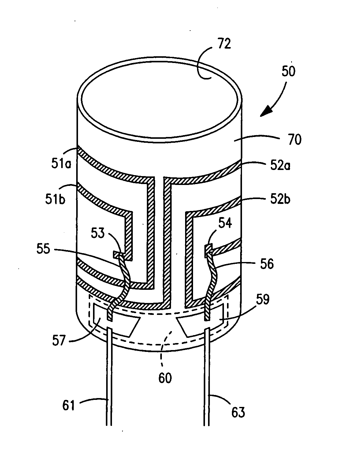
[0007]This present work is directed to a balanced NMR coil structure featuring lumped capacitance(s) disposed directly on the coil former as an integral component of the coil former, but remaining separate and independent of the inductive members of the coil. These capacitances comprise portions of the tune and match capacitance networks for the balanced resonant coil (resonator) as well as the capacitance required for support of the resonant condition. Capacitance networks are required with NMR probes for tuning and matching the resonator to its RF source or sink. A basic result of this arrangement is the reduction of RF voltage difference between the coil leads, and several further results deriving from this voltage reduction, thereby adding utility to NMR probe design and operation. The capacitance network is ordinarily located well outside and somewhat remote from the sensitive volume defined by the coil geometry. This arrangement avoids disturbing influences close to the sensitive volume.
[0008]One or more capacitances, disposed immediately proximate to coil terminals are built directly on the coil form. The conductive material for this purpose is, preferably, susceptibility matched, as is the coil itself, to avoid discontinuities in the magnetic susceptibility distribution in this region. These capacitances provide resonant circuit capacitance and / or tune and match functions for the coil with the result of providing a relatively lower RF voltage difference between the RF leads as compared with the standard practice of locating a parallel lumped capacitance remote from the coil terminals and away from the sensitive volume, as well as remotely locating capacitance networks for tuning and matching the coil to its source and / or sink. The higher RF potential along conventional relatively lengthy leads from the capacitance networks enhance radiative losses and thus lower efficiency. In the context of modern cryogenic NMR probes, the Q of the coil is of the order of as much as several times 103. Because of the very high Q, the RF voltage at the coil terminals can be very large compared to the voltage realized at the RF input at selected power and matched to 50 ohms. A peculiarity of the cryogenic context, for this apparatus, is the near vacuum environment of the coil cryostat. Taken together with the relatively high RF electric field between leads, these environmental effects contribute noise from ionization / recombination processes of the residual gasses in the vacuum spaces due to the high RF power density in operation. Consequently, the reduced RF voltage diminishes this noise constituent.
[0009]Further, in the cryogenic context, the preferred substrate for the integrated capacitance structure of the present work, is sapphire, a material of excellent dielectric and thermal conductivity. The structure described here provides a very intimate thermal coupling of capacitive constituents to the relatively large sapphire coil form resulting in improved thermal transport of heat away from the resonator.

Problems solved by technology

The higher RF potential along conventional relatively lengthy leads from the capacitance networks enhance radiative losses and thus lower efficiency.
Taken together with the relatively high RF electric field between leads, these environmental effects contribute noise from ionization / recombination processes of the residual gasses in the vacuum spaces due to the high RF power density in operation.
Consequently, the reduced RF voltage diminishes this noise constituent.

Method used


Image

  • NMR coil having integrated capacitive structures
  • NMR coil having integrated capacitive structures
  • NMR coil having integrated capacitive structures

Examples


Embodiment Construction

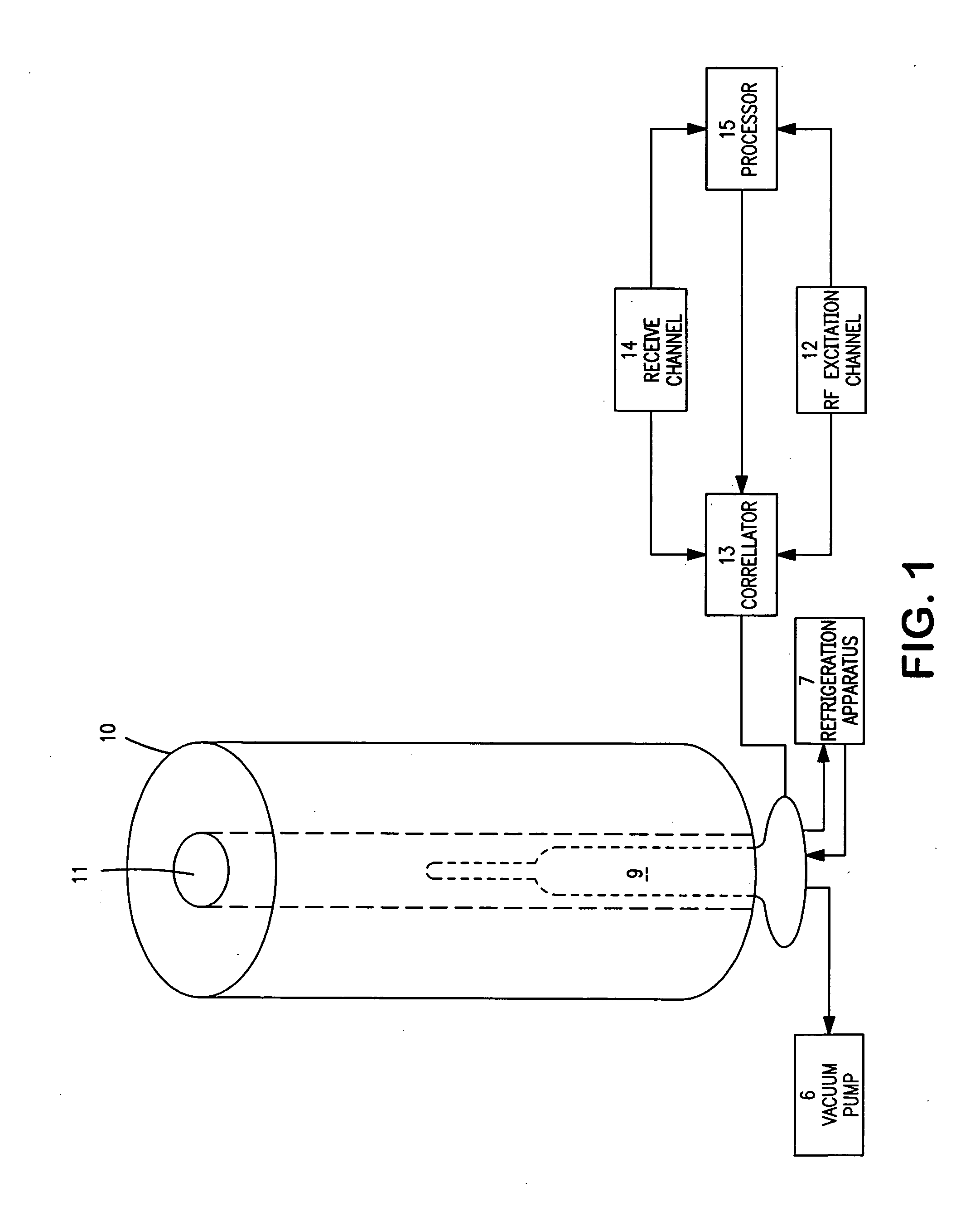
[0017]FIG. 1 serves to illustrate conceptually the context of this work within an NMR system. An NMR probe 9 is disposed within the bore 111 of a superconducting magnet 10. A sample for analysis is presented in a sample vessel (not shown) inserted in the probe 9. The probe 9 inductively couples to the nuclear spins of the sample for excitation through at least a first RF excitation channel 12 and separately for signal acquisition through a receive channel 14. Excitation and receive functions often share a common probe coil for non-concurrent operation through correllator 13, but multiple coils are frequently employed to serve different functions, such as to furnish spin decoupling, field-frequency lock, and the like. The receive channel ordinarily includes a preamplifier and RF demodulator, phase detector, analog-to-digital conversion (ADC) and various signal processing apparatus together with a digital processor 15 to effect averaging, Fourier transformation, storage and the like. ...


PUM


Abstract

An NMR probe includes a coil former on which the resonant capacitance and / or tune and match capacitances are integrally implemented. Adjustable capacitances are realized in combination with a composite former including a slip glass for support of a capacitor plate. Particular advantages are realized in the context of cryostatic NMR probes.

Description

BACKGROUND OF THE INVENTION[0001]This work is in the field of nuclear magnetic resonance (NMR) and relates particularly to the NMR probe, that is to say, a structure for inductive coupling of nuclear spins to the excitation and signal acquisition channels of an NMR apparatus.[0002]The central component of an NMR probe is a resonator, or tuned circuit for inductively coupling to the nuclear spins of a sample introduced into the resonator. The resonator is frequently referenced as a “coil” comprising axially extending inductive members distributed azimuthally around, and radially outside the sample vessel. The resonance properties of the coil are established with capacitive reactance furnished in parallel or in series with the coil. The inductive members may be interconnected together to form diverse coil topologies, such as saddle coils, birdcage coils, millipede coils, spirals, series or parallel Helmholtz pairs, etc. The capacitive reactance necessary for the resonance condition is...

Claims


Application Information

Patent Timeline
Patent Type & Authority Applications(United States)
IPC IPC(8): G01R33/36
CPCG01R33/34007G01R33/3628G01R33/34046
Inventor GOETZ, JONLLANOS, WILLIAM
Owner AGILENT TECH INC
Learn More