Supercharge Your Innovation With Domain-Expert AI Agents!

Frame Synchronizer, Synchronization Method of Frame Synchronizer, Image Processing Apparatus, and Frame Synchronization Program

a synchronization method and frame synchronization technology, applied in the field of frame synchronizer, synchronization method of frame synchronizer, image processing apparatus, and frame synchronization program, can solve the problems of buffer overflow or underflow in the buffer memory, image quality to be deteriorated, etc., to reduce power consumption, suppress the generation, and less capacity required for the buffer memory

Inactive Publication Date: 2008-06-12
PIONEER CORP
View PDF3 Cites 5 Cited by
  • Summary
  • Abstract
  • Description
  • Claims
  • Application Information

AI Technical Summary

Benefits of technology

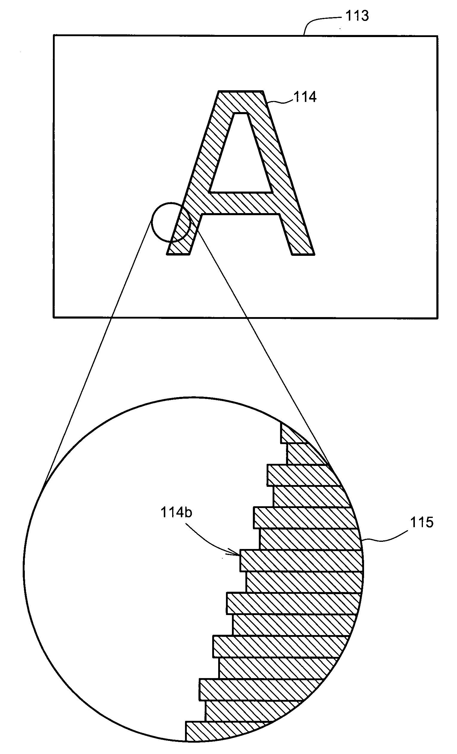
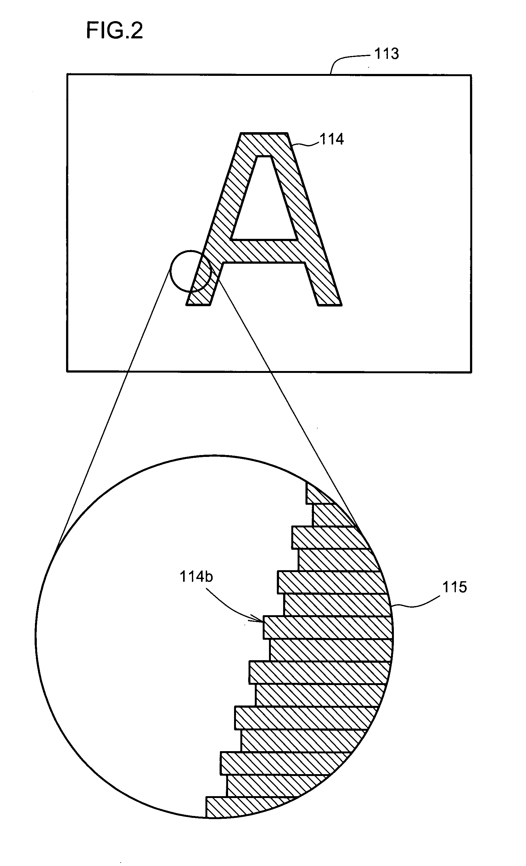
[0007]In view of the foregoing, it is an object of the present invention to provide a frame synchronizer, synchronization method, image processing apparatus and frame synchronization program for suppressing the generation of the above mentioned jaggy. It is another object of the present invention to provide a frame synchronizer, synchronization method, image processing apparatus and frame synchronization program that are capable of providing less capacity required for a buffer memory and reducing power consumption, as well as suppressing the generation of the above mentioned jaggy.

Problems solved by technology

The frequency shift can keep for a predetermined time, thus causing a buffer overflow or underflow in the buffer memory.
However, there is a problem with the possible method that the contour of the image edge portion becomes blurred, thereby causing image quality to be deteriorated.

Method used


Image

  • Frame Synchronizer, Synchronization Method of Frame Synchronizer, Image Processing Apparatus, and Frame Synchronization Program
  • Frame Synchronizer, Synchronization Method of Frame Synchronizer, Image Processing Apparatus, and Frame Synchronization Program
  • Frame Synchronizer, Synchronization Method of Frame Synchronizer, Image Processing Apparatus, and Frame Synchronization Program

Examples


Embodiment Construction

[0028]Various embodiments of the present invention will now be described.

[0029]FIG. 3 is a block diagram depicting a configuration of an image processing apparatus 1 that comprises a frame synchronizer 10 according to an embodiment of the present invention. This image processing apparatus 1 comprises the frame synchronizer 10, an encoder 20, a clock generator 21 and an analog processing unit 30. The frame synchronizer 10 includes an analog processing unit 11, a digital processing unit 12, a buffer memory 14 and a controller (memory control section) 15. The buffer memory 14 further includes a first buffer memory (field memory) 13A and a second buffer memory (line memory) 13B.

[0030]A synchronization signal SYNC_A and an analog video signal VIN synchronized with a synchronization signal SYNC_A are supplied to the frame synchronizer 10. In the present embodiment, the analog video signal VIN and the synchronization signal SYNC_A are separately supplied to the frame synchronizer 10. Alter...


PUM


Abstract

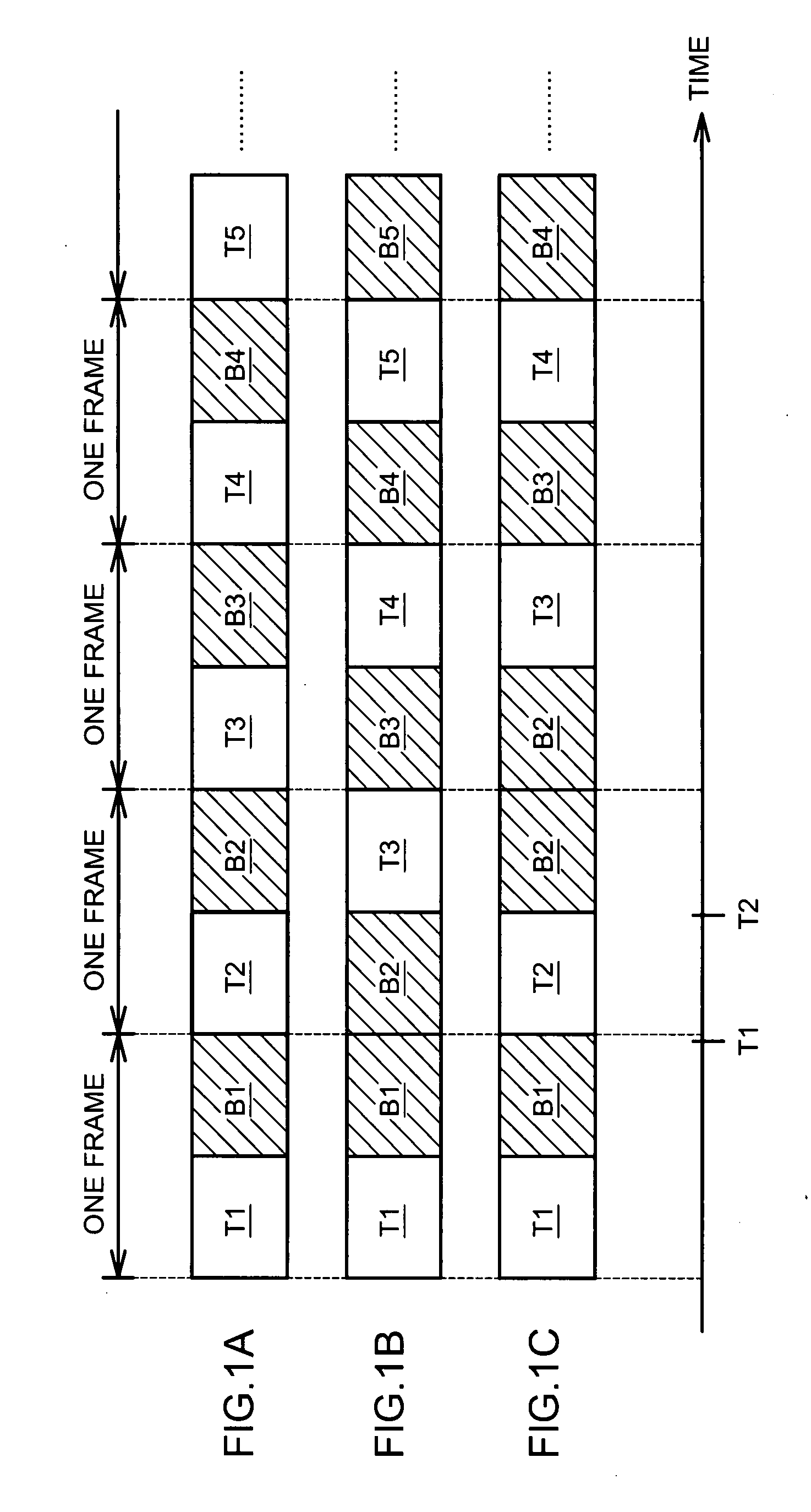
Disclosed is a frame synchronizer 10 capable of suppressing the generation of a jaggy phenomenon without deteriorating image quality. The frame synchronizer comprises a buffer memory for sequentially storing an input video data stream supplied in synchronization with a first synchronization signal, and a memory control section for reading video data from the buffer memory in synchronization with a second synchronization signal. Before a remaining capacity of the buffer memory reaches a predetermined lower limit, the memory control section reads one field of first and second fields in an area starting from a predetermined start line and reads the other field in an area starting from a predetermined first start line, the first field containing pixel data on even number lines of each frame, and the second field containing pixel data on odd number lines of each frame. When the remaining capacity of the buffer memory reaches the predetermined lower limit, the memory control section reads only the other field in an area starting from a second start line that is shifted by one horizontal line from the predetermined first start line.

Description

TECHNICAL FIELD[0001]The present invention relates to a frame synchronizer for converting a video signal synchronized with a synchronization signal input from an external signal source, into a video signal synchronized with another synchronization signal, and relates to technologies associated to the frame synchronizer.BACKGROUND ART[0002]Encoders that perform digital-processing on video signals are widely integrated into recording / reproducing apparatus capable of recording video signals onto a high-capacity recording medium such as an optical disk, or into communication devices capable of receiving broadcast signals and / or radio signals. In the NTSC (National Television System Committee) system, for example, three types of synchronization signals (i.e., a vertical synchronization signal, a horizontal synchronization signal and a color synchronization signal) are multiplexed into an analog video signal. To perform digital-processing on such an analog video signal, it is required tha...

Claims


Application Information

Patent Timeline
IPC IPC(8): H04N5/04
CPCH04N5/04
Inventor HASHIMOTO, KAZUNORI
Owner PIONEER CORP
Features
  • R&D
  • Intellectual Property
  • Life Sciences
  • Materials
  • Tech Scout
  • Unparalleled Data Quality
  • Higher Quality Content
  • 60% Fewer Hallucinations
Learn More