Method And System For Optical Imaging And Ranging

a technology of optical imaging and ranging, applied in the field of optical imaging, can solve the problems of limiting the depth resolution of classical apertures, and none of these methods can achieve super-resolution beyond the depth of field, and achieve the effect of optimizing depth estimation and maximizing fisher information

Active Publication Date: 2008-06-12
TECHNION RES & DEV FOUND LTD +1
View PDF17 Cites 70 Cited by
  • Summary
  • Abstract
  • Description
  • Claims
  • Application Information

AI Technical Summary

Benefits of technology

[0016]The mask used in the imaging system may maximize Fisher information and / or may be statically or dynamically changed. The mask may also comprise a diffractive optical element, a continuous phase mask, a hologram, a computer generated hologram, an amplitude mask, a kinoform and / or a combination thereof. The sensor array may comprise a CCD, CID, and CMOS device.
[0021]The distance of objects to an optical system may be estimated in conjunction (if so desired) with other parameters such as the object brightness and object transverse position. An optical mask such as a diffractive optical element, continuous phase mask, hologram, or amplitude mask is placed within the optics in front of a sensor array such as a CCD, CID, or CMOS device. The optical mask encodes the three-dimensional response of the system. The mask is designed to optimize depth estimation, for example, by maximizing Fisher information. A particular implementation creates a point spread function (“PSF”) that rotates as a function of the object position. The image or images are digitally processed to recover both a depth map of the scene and other parameters such as image brightness. The task of the digital process is to implement an estimation algorithm selected from a variety of methods according to system tradeoffs between processing time and estimate accuracy. The system and method provide depth resolution beyond the depth-of-field limit imposed by the numerical aperture of the system.

Problems solved by technology

Nevertheless, diffraction limits the depth resolution when classical apertures are used.
None of these methods can achieve super-resolution beyond the depth of field, which is limited by the numerical aperture of the system.

Method used


Image

  • Method And System For Optical Imaging And Ranging
  • Method And System For Optical Imaging And Ranging
  • Method And System For Optical Imaging And Ranging

Examples


Embodiment Construction

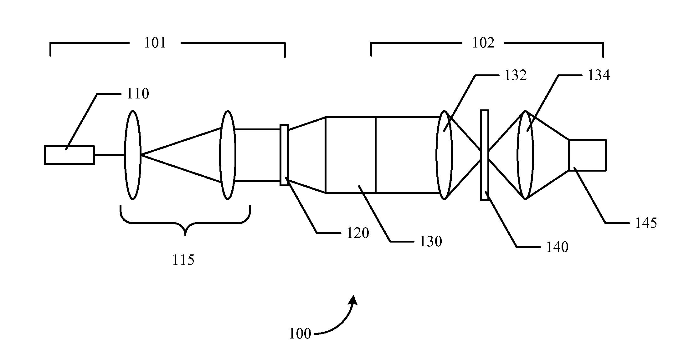
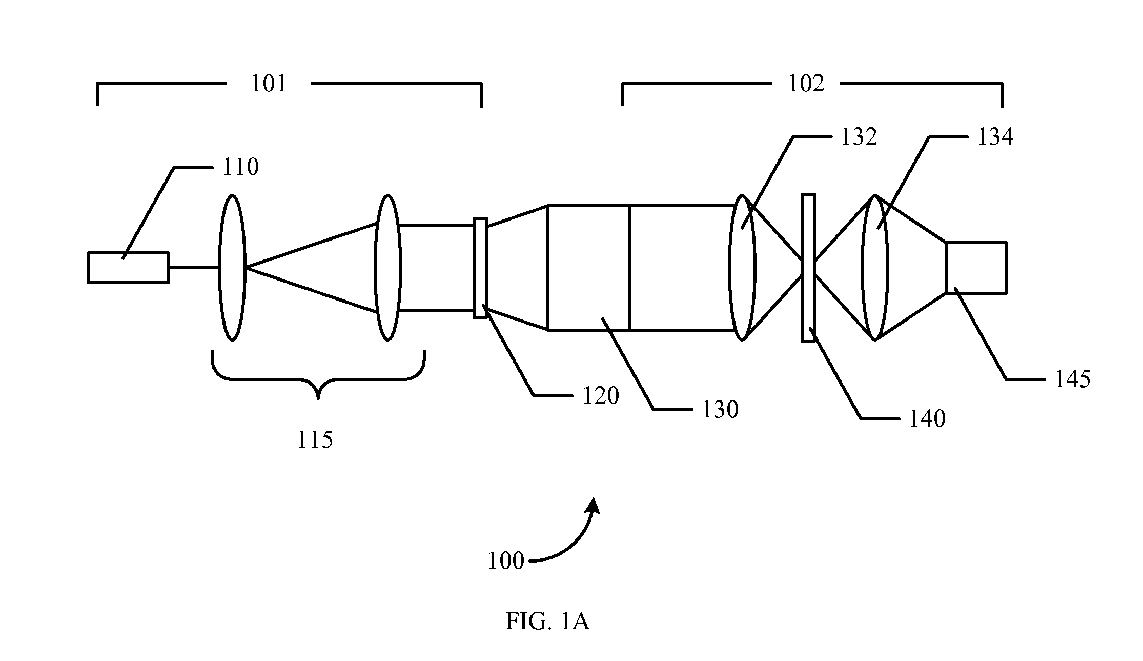
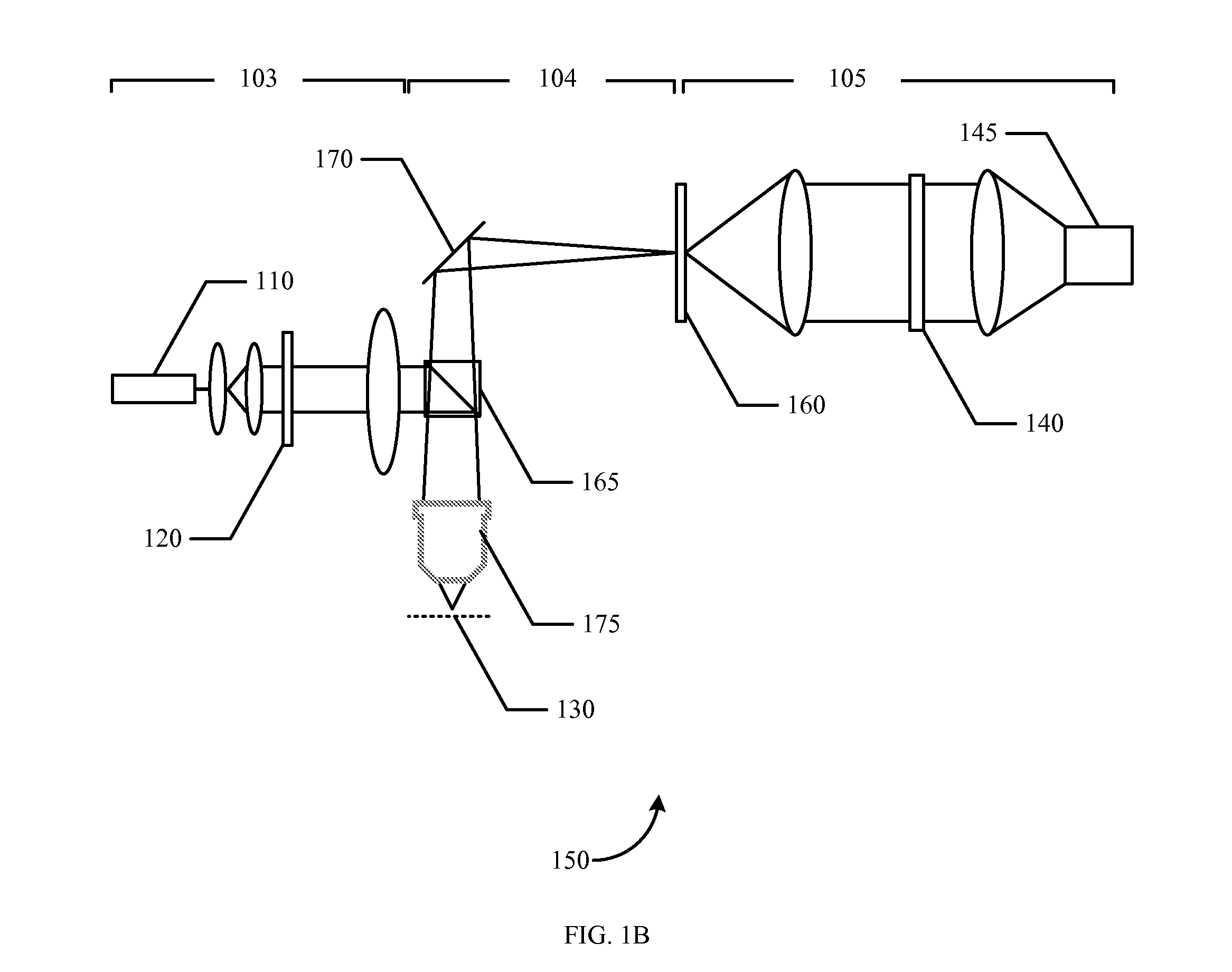
[0027]In one embodiment of the invention, methods and systems are provided for optical imaging and ranging based on engineering the point spread function (“PSF”) to achieve enhanced performance in the task of depth estimation. The PSF is optimized to enhance the discrimination of depth by reducing the uncertainty in depth estimation after an inversion algorithm performed in a (typically digital) computer. Physical design and postprocessing (or inversion) algorithms are matched to the specific task of depth estimation. Therefore, the PSF is optimized with respect to a mathematical measure such as Fisher information. However, other measures of good depth discrimination, such as mutual information or entropy among optical intensity distributions in depth, are also possible.

[0028]This principle can be applied to visible optical radiation, infrared or ultraviolet. It can also be used for any other electromagnetic radiation such as microwaves or radio waves. Moreover, it can be used with ...


PUM


Abstract

The distance of objects to an optical system is estimated. An optical mask such as a diffractive optical element, continuous phase mask, hologram, amplitude mask, or combination thereof is placed within the optics in front of a sensor array such as a CCD, CID or CMOS device. The optical mask encodes the three-dimensional response of the system. The mask is designed to optimize depth estimation, for example, by maximizing Fisher information. A particular implementation creates a point spread function (“PSF”) that rotates as a function of the object position. The image or images obtained with different PSFs may be digitally processed to recover both a depth map of the scene and other parameters such as image brightness. The digital processing used to recover the depth map of the object may include deconvolution of a PSF from detected images.

Description

CROSS-REFERENCES TO RELATED APPLICATIONS[0001]This application is a non-provisional, and claims the benefit, of commonly assigned U.S. Provisional Application No. 60 / 803,938, filed Jun. 5, 2006, entitled “Method And System For Passive Optical Imaging And Ranging,” the entirety of which is herein incorporated by reference for all purposes.BACKGROUND OF THE INVENTION[0002]This application relates generally to optical imaging. More specifically, this application relates to methods and systems for optical imaging and ranging.[0003]In most situations, when dealing with recovering the three-dimensional structure of an object or a scene, the objects are opaque. Such is the case when viewing everyday objects such as a tool or a person. There are usually two variables of interest at each image pixel: the surface brightness (reflectance), and its distance from the camera (depth). These two variables (per pixel) are commonly recovered based on two input images.[0004]There are several known met...

Claims


Application Information

Patent Timeline
Patent Type & Authority Applications(United States)
IPC IPC(8): G01C3/08
CPCG01C3/08
Inventor PIESTUN, RAFAELCOGSWELL, CAROL J.GREENGARD, ADAM D.SCHECHNER, YOAV Y.
Owner TECHNION RES & DEV FOUND LTD
Why Eureka
Try Eureka