
Flow-through apparatus for microscopic investigation of dissolution pharmaceutical solids

a flow-through apparatus and dissolution solid technology, applied in the direction of instruments, liquid displacement, separation processes, etc., can solve the problems of difficult prediction, hydrodynamic impact study, and insufficient understanding of the hydrodynamics of most standard dissolution test methods

Inactive Publication Date: 2008-06-12
UNIV OF CONNECTICUT
View PDF6 Cites 12 Cited by
  • Summary
  • Abstract
  • Description
  • Claims
  • Application Information

AI Technical Summary

Benefits of technology

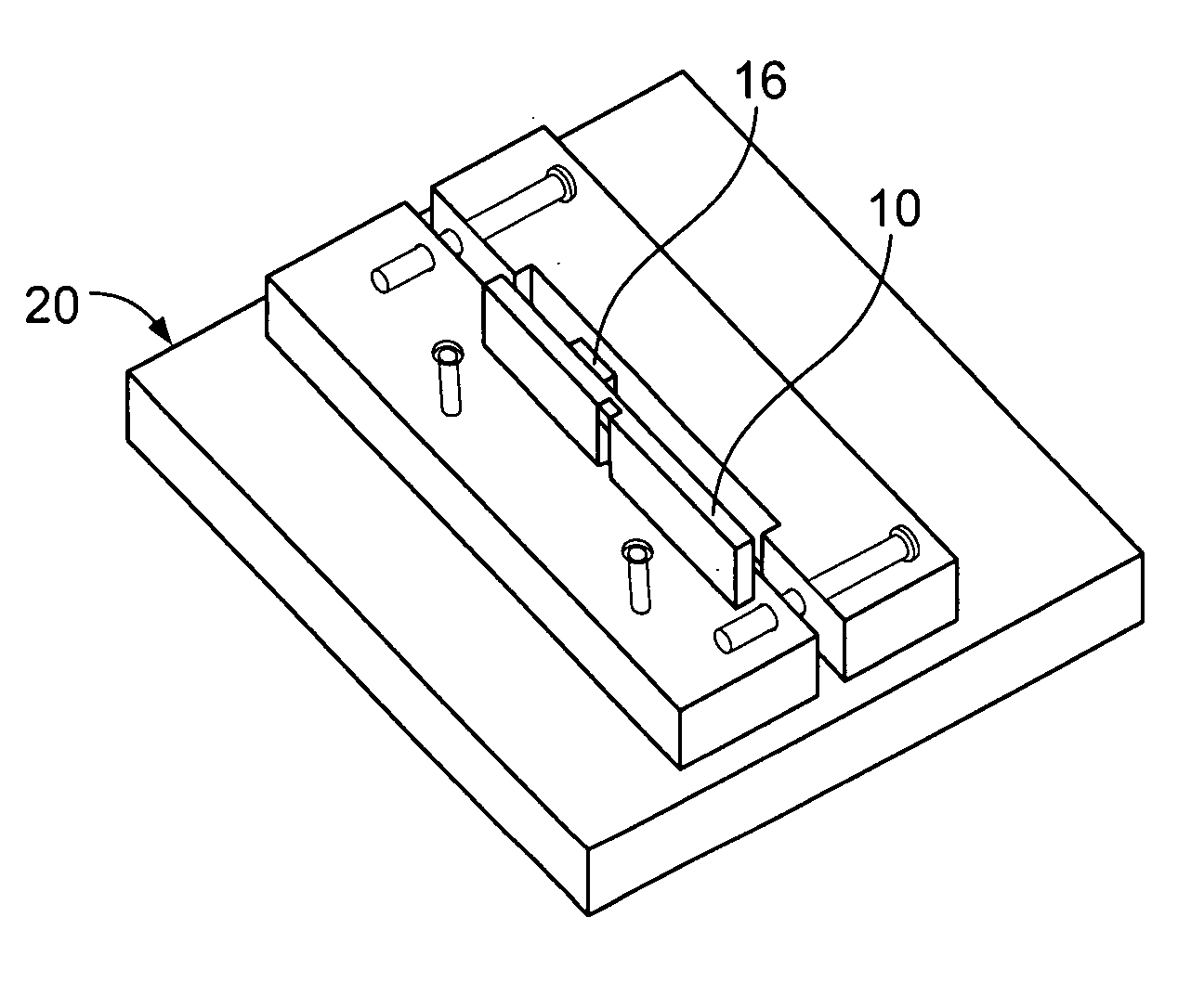
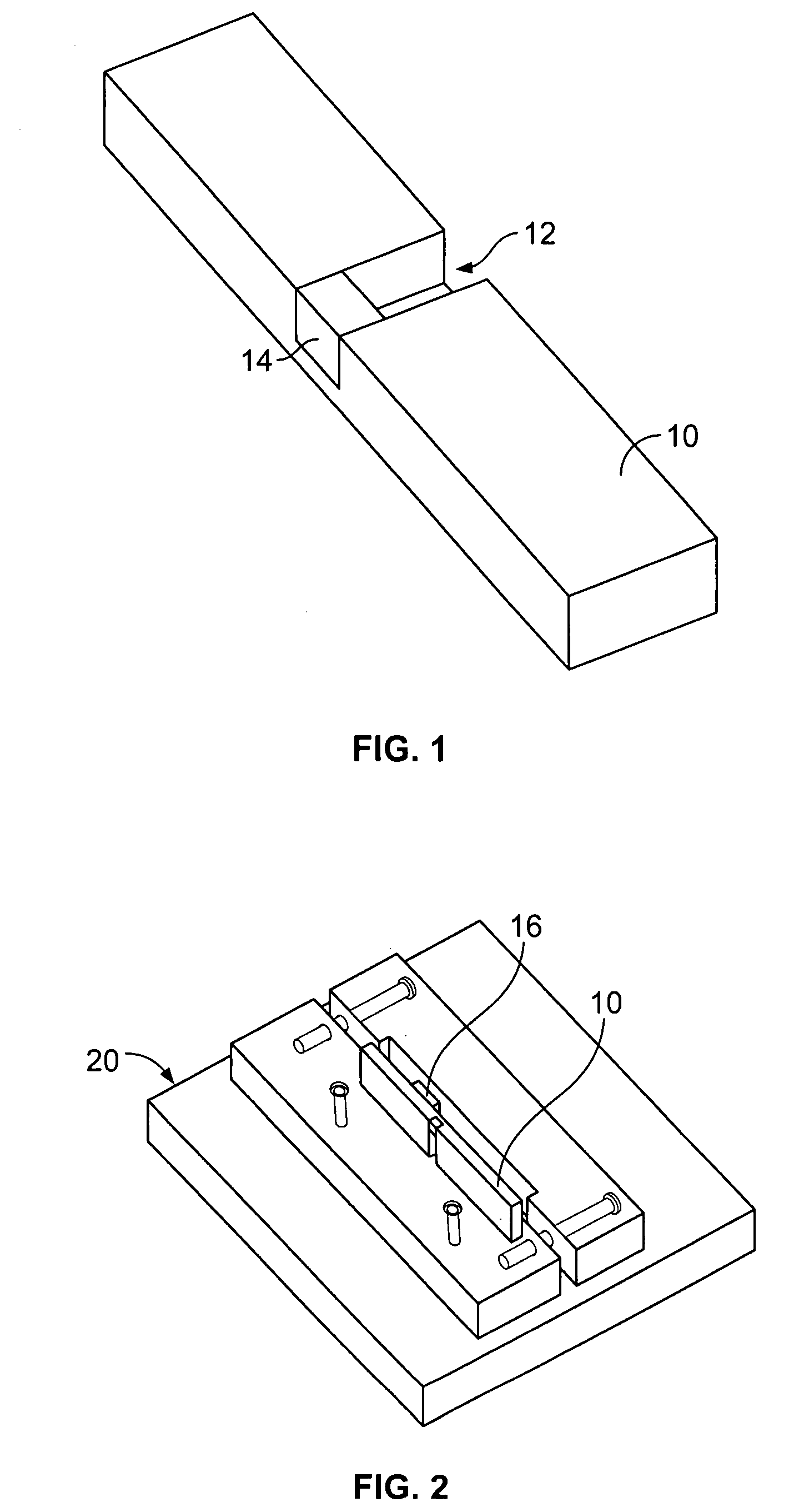
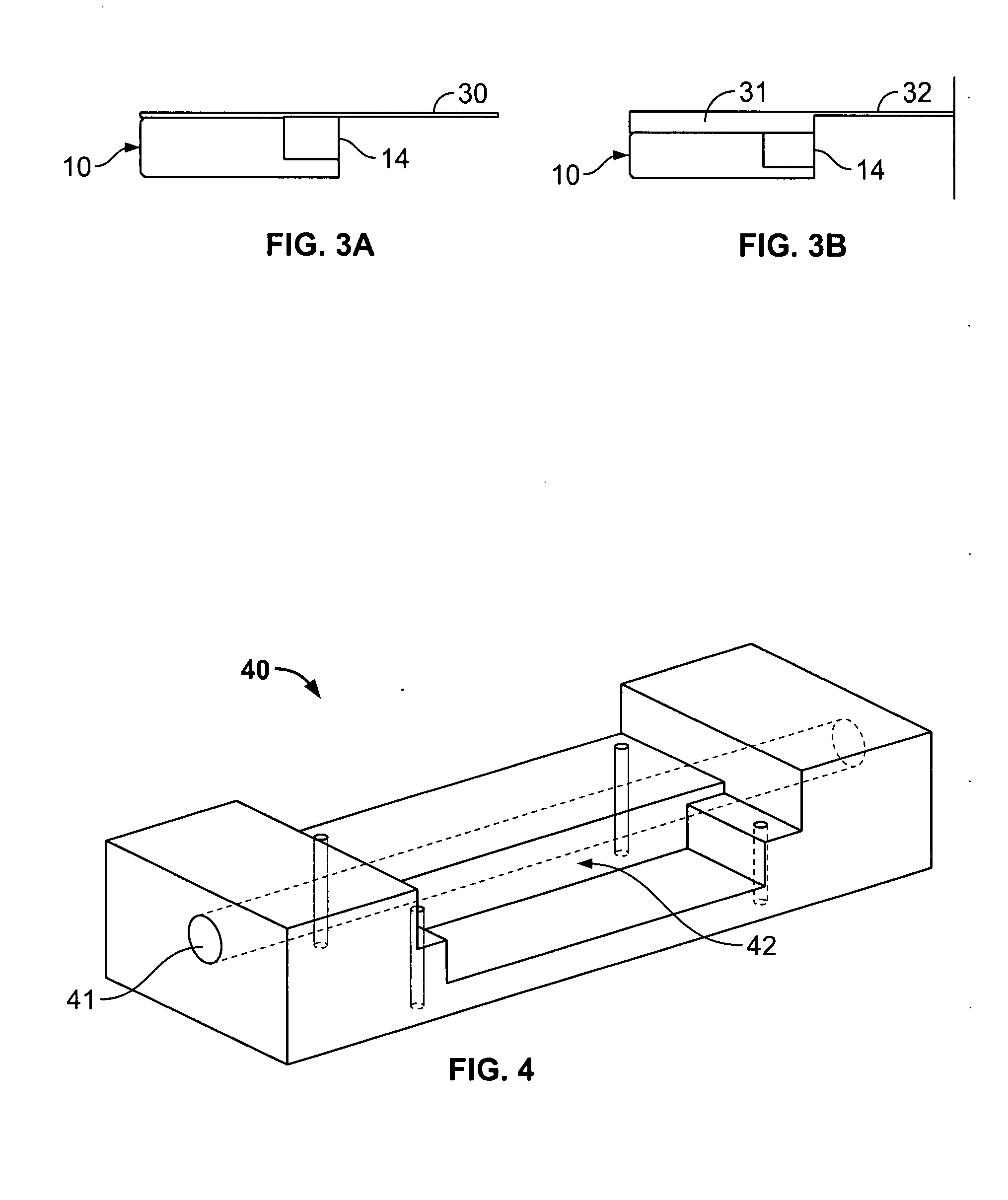
[0016]In an exemplary apparatus associated with the present disclosure, the frame further includes a second glass plate positioned to space the sample away from the first glass plate that covers the flow-through channel. Typically, at least one of the glass plates are microscope coverslips that securely fit within the frame and adapted to cover a custom cut glass

Problems solved by technology

Hydrodynamics of most standard dissolution test methods are not fully understood.
Lack of hydrodynamic data makes studying the hydrodynamic impact on any interesting phenomena that could arise (e.g., salt form changes, polymorph changes) challenging in predicting bioavailability in humans.
For example, using current systems / methods, when unexpected change in dissolution rates during standard testing occurs, typically an analyst cannot easily observe physical changes in real time associated with changes in dissolution.
Also, current dissolution testing systems / methods require large amounts of test sample.
This creates a serious burden on a typical research analyst or research group since they may receive only a few milligrams of a new compound designated to undergo several tests.
These standard methods, however, fail to appreciate or consider the exact hydrodynamics since the fluid flow characteristics are complicated and time dependent.
In each of the aforementioned descriptions, whether the hydrodynamics are fully understood or not, none describes a system capable of visualizing the pharmaceutical solid during dissolution.
While visualization is possible using the aforementioned systems / methods, the disclosed systems / techniques fail to appreciate or consider complete characterization of the hydrodynamics of the system.
Similarly, various techniques have been described for a flow-through dissolution apparatus that inadequately address hydrodynamics.
When choosing a salt form, aqueous solubility alone is not enough information to understand the full solubility advantage of a salt form due to the propensity to convert to a lower solubility form during solubility studies.
Currently, the conditions under which these phenomena should be optimally studied are not fully understood.
The hydrodynamics of most standard pharmaceutical dissolution test methods are not fully understood, which makes studying the hydrodynamic impact on any interesting phenomena that could arise (e.g., salt form changes, polymorph changes) nearly impossible.
When there is an unexpected change in dissolution rates during standard testing, the scientist cannot easily observe any visual changes that accompany such a change.
More importantly, currently available standard methods require a large amount of material.

Method used


Image

  • Flow-through apparatus for microscopic investigation of dissolution pharmaceutical solids
  • Flow-through apparatus for microscopic investigation of dissolution pharmaceutical solids
  • Flow-through apparatus for microscopic investigation of dissolution pharmaceutical solids

Examples


example 1

[0089]Flow profiles through rectangular channels of 4×4 mm, 6×2 mm, and 4×2 mm were analyzed using CFD. Prior to using CFD, however, the proper geometries for exemplary channels were created using GAMBIT software (Fluent, Inc., Lebanon, N.H.). 3D rectangular volumes with various cross sectional geometries (4×4 mm, 4×2 mm, 6×2 mm) were created. Simple rectangular meshes were set up to consist of around 150,000 nodes, fine enough to accurately represent the velocity profiles. This mesh was of constant interval size, which led to convergence of the solution in CFD in less than 1 hour. Boundary types were also selected in GAMBIT. Inlets were set as velocity inlets, outlets were pressure outlets, and all walls were set as walls.

[0090]In CFD, various parameters were set up for each case. The boundary conditions set in GAMBIT were further described based on what kind of tests were to be performed. For the initial velocity tests, the energy equation was not solved. Material properties were ...

example 2

[0099]Shear stresses and rates over a compact surface were modeled using CFD for comparison to existing dissolution apparatus and in vivo. In an existing dissolution device, a USP II apparatus, shear stresses and shear rates have been modeled using CFD. (See, e.g., Kukura, J., J. L. Baxter, and F. J. Muzzio, Shear distribution and variability in the USP Apparatus 2 under turbulent conditions, International Journal of Pharmaceutics, 2004, 279(1-2): p. 9-17.) In addition to these reported results, a paper by Abrahamsson models the shear stresses experienced by a compact in the human fed stomach by CFD. (See, e.g., Abrahamsson, B., et al., A Novel in Vitro and Numerical Analysis of Shear-Induced Drug Release from Extended-Release Tablets in the Fed Stomach, Pharmaceutical Research, 2005, 22(8): p. 1215-1226.) These results were taken into consideration as a comparison for the shear stresses experienced in a flow-through apparatus associated with the present disclosure.

[0100]Abrahamsson...

example 3

[0103]It is desirable to compare fluid flow in an exemplary apparatus associated with the present disclosure with that in the rotating disk apparatus to correlate existing data. The rotating disk or Wood's Die apparatus was chosen as a comparator because the hydrodynamics and mass transport are well known and characterized. (See, e.g., Levich, V. G., Physicochemical Hydrodynamics. 1962. 700 pp.) To establish a relationship between rotating disk speed and volumetric flow rate for an exemplary channel of a flow-through apparatus, fluxes are equated in each apparatus.

Flux of a drug from a rotating disk is described as:

J=0.62D2 / 3ν−1 / 6ω1 / 2Cs  (Equation 5)

[0104]The dissolution rate for a drug compact in a rectangular channel is:

R=1.468Q1 / 3D2 / 3Csb(L2H2W)1 / 3(Equation6)

[0105]To convert this into a flux, divide by area.

J=1.468A-1Q1 / 3D2 / 3Csb(L2H2W)1 / 3(Equation7)

[0106]When we equate the flux in Equation 5 and Equation 7, solve for ω1 / 2 and substitute the flow cell tablet area for A, (6.8*10−6 m...


PUM

PropertyMeasurementUnit
Thicknessaaaaaaaaaa
Thicknessaaaaaaaaaa
Thicknessaaaaaaaaaa

Abstract

The present disclosure is directed to an apparatus and method for studying dissolution of a compact sample. The compact sample is typically a pharmaceutical drug sample. A flow-through apparatus includes a frame defining a flow-through channel, a removable insert having a drug sample, the insert positioned within the frame such that a fluid interacts with the sample when the fluid passes through the flow channel. The frame has an opening on the top side to allow a glass plate, typically a microscope cover slip to be positioned within the frame and allow viewing of the fluid flow and interaction with the drug sample. The hydrodynamics of the fluid flow are either known or computed. Thus, dissolution can be studied and observed in view of hydrodynamic characteristics. Typically, only a small amount of sample is necessary for a study. The flow-through apparatus is designed to fit on a microscopy stage and allow visual observation of the fluid / sample interaction.

Description

BACKGROUND[0001]1. Technical Field[0002]The present disclosure relates to systems and methods for investigating dissolution of pharmaceutical solids.[0003]2. Background Art[0004]Dissolution of a drug from the solid state in a solid oral dosage form is a key step in the absorption and eventual therapeutic effect of a drug. Once a potential drug has been identified, a proper solid form (e.g., polymorph, salt form) must be chosen. In choosing a proper solid form, certain behavioral properties must be taken into consideration such as, for example, dissolution rates, equilibrium solubility, physical and chemical stability. Dissolution rates depend on the hydrodynamics of the fluid adjacent to the solid state drug. Hydrodynamics of most standard dissolution test methods are not fully understood.[0005]Lack of hydrodynamic data makes studying the hydrodynamic impact on any interesting phenomena that could arise (e.g., salt form changes, polymorph changes) challenging in predicting bioavaila...

Claims


Application Information

Patent Timeline
IPC IPC(8): B01D11/02
CPCG01N21/0317G01N21/0332G01N21/05G01N2201/0245G01N21/272G01N2021/0342G01N2021/056G01N21/09
Inventor BOGNER, ROBIN H.BERGMAN, THEODORE L.GRECO, KRISTYNMICHAELS, DEREK J.CHAWARSKI, SZYMON J.
Owner UNIV OF CONNECTICUT
Learn More