
Process for increasing hydrogen recovery

a hydrogen recovery and hydrogen technology, applied in the direction of chemistry apparatus and processes, separation processes, dispersed particle separation, etc., can solve the problems of undesirable side reactions, inability to route vent gas to the hydrocarbon conversion unit, and the amount of mass flow in such vessels to justify the purchase and installation of such equipmen

Inactive Publication Date: 2008-06-19
UOP LLC
View PDF16 Cites 9 Cited by
  • Summary
  • Abstract
  • Description
  • Claims
  • Application Information

AI Technical Summary

Benefits of technology

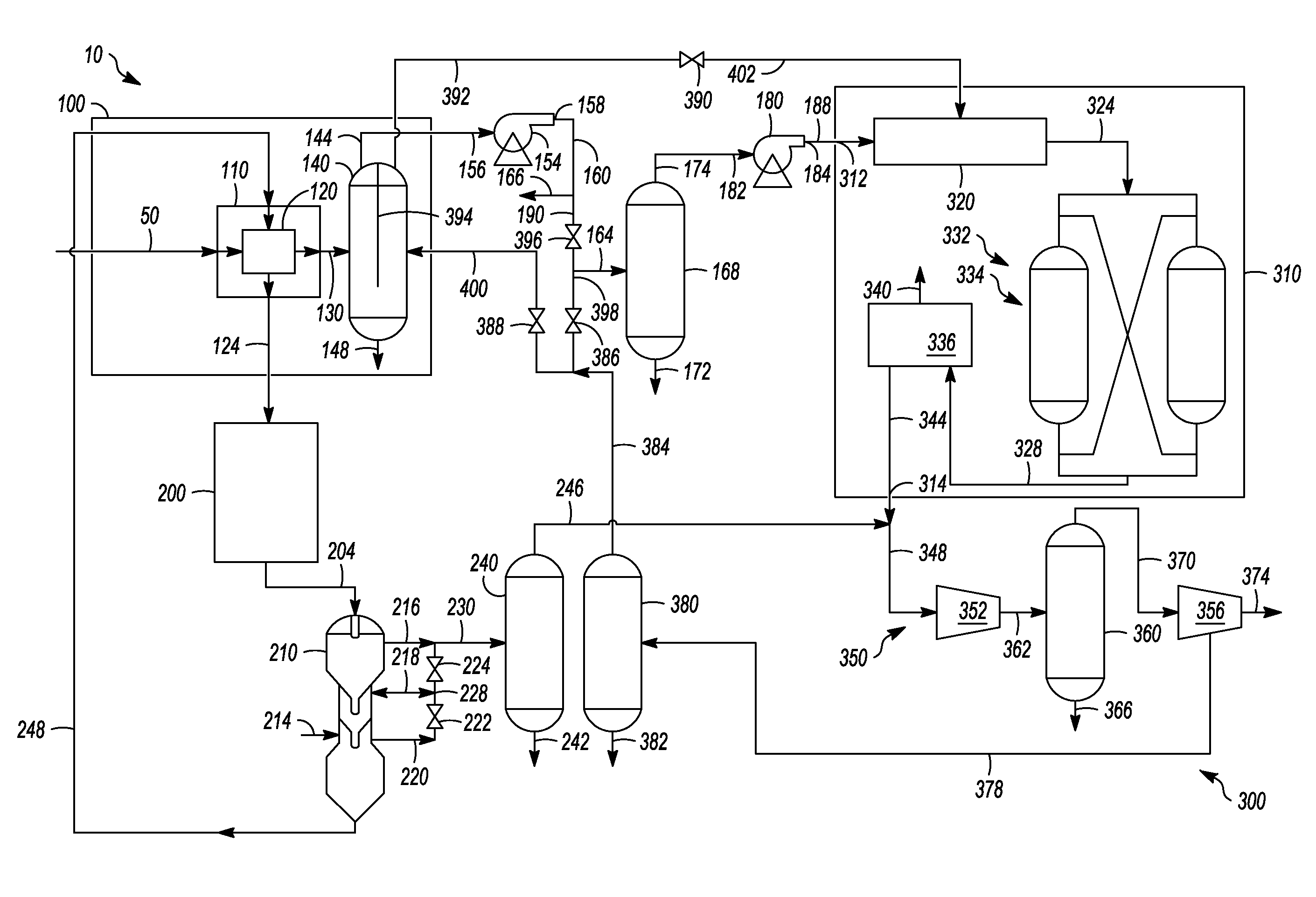
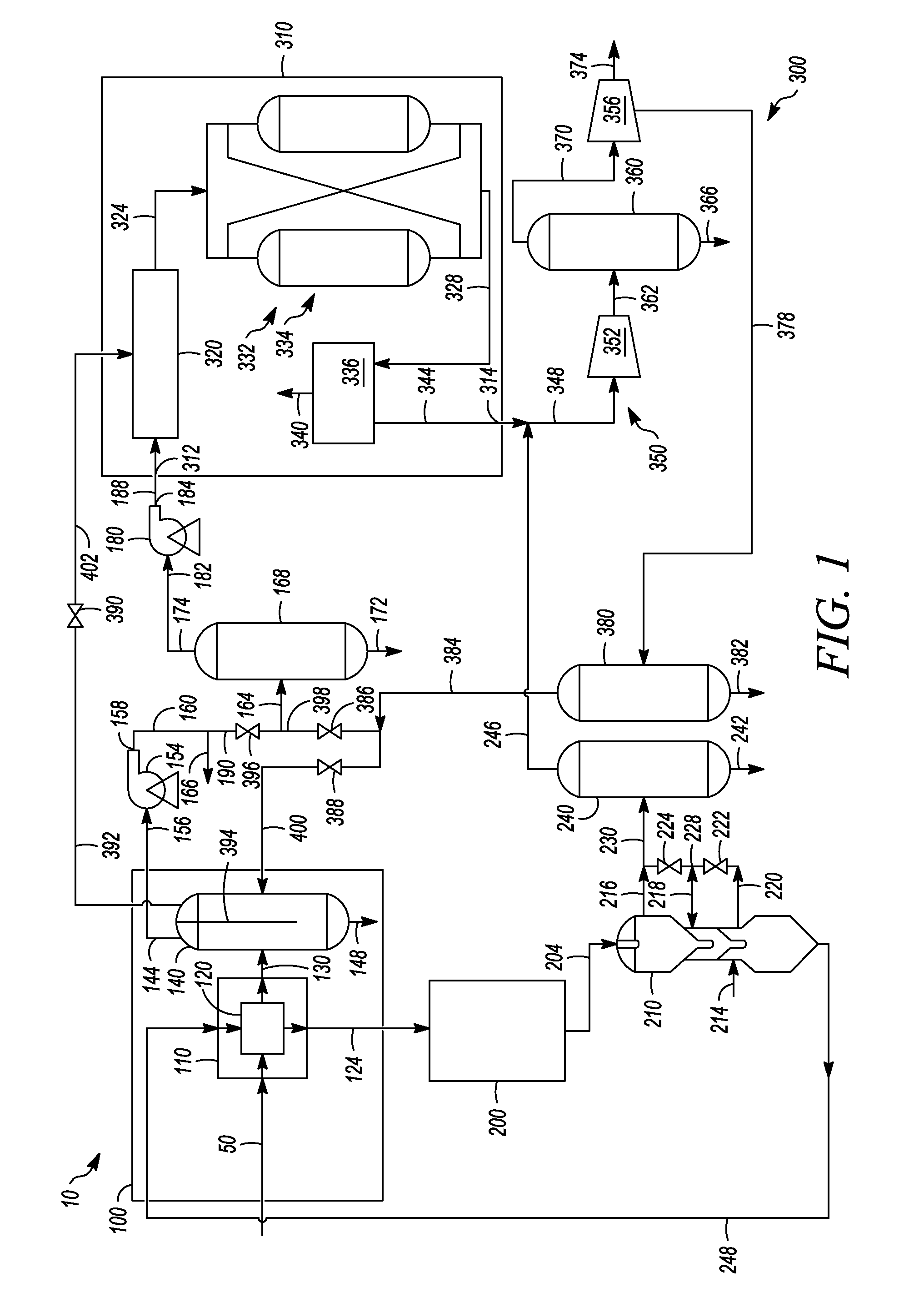
[0009]As a consequence, the present invention allows the recovery of hydrogen from sources that are at a lesser pressure than those at other units, such as a hydrocarbon conversion zone. Thus, the embodiments disclosed herein allow the recovery of hydrogen that might otherwise be sent to fuel gas. In particular, unrecovered hydrogen streams are generally sent to the fuel gas, which is typically a lower valued product than if recovered and purified. What is more, the embodiments disclosed herein permit the modification of any existing hydrocarbon conversion unit to recover a hydrogen gas stream without the additional expense of equipment such as a compressor.

Problems solved by technology

Thus, this vent gas cannot be routed to the hydrocarbon conversion unit unless fluid transport equipment is installed, such as a pump or compressor.
Typically, the amount of mass flow in such vessel vent gas streams do not justify economically the purchase and installation of such equipment.
In addition, often these vent gas streams have impurities.
Such impurities can lead to undesirable side reactions in the hydrocarbon conversion unit.

Method used


Image

  • Process for increasing hydrogen recovery
  • Process for increasing hydrogen recovery

Examples


Embodiment Construction

[0013]The embodiments disclosed herein allow a gas (hereinafter may be referred to as a “second gas”) containing hydrogen at a pressure lower than a hydrocarbon conversion zone to be recycled in a tail gas recycle circuit that can include a hydrogen purification zone. Generally, the hydrogen purification zone receives a gas (hereinafter may be referred to as a “first gas”) containing hydrogen from a hydrocarbon conversion zone where typically a hydrogen product stream can be at least partially recycled back to the hydrocarbon conversion zone while producing a tail gas that is at least partially recycled. The second gas can be combined with the tail gas to be recycled back to the hydrogen purification zone where at least a portion is recovered as the hydrogen product stream, and as mentioned above, sent back to the hydrocarbon conversion zone.

[0014]Referring to FIG. 1, a refinery or a petrochemical production facility 10 can include a hydrocarbon conversion zone 100, a catalyst regen...


PUM


Abstract

A process for increasing hydrogen recovery can include:(a) sending a first gas from a hydrocarbon conversion zone at a first pressure to a hydrogen purification zone;(b) combining a second gas from a particle transport vessel at a second pressure less than the first pressure with a tail gas from the hydrogen purification zone to create a combined stream; and(c) recycling at least a portion of the combined stream to an inlet of the hydrogen purification zone.

Description

FIELD OF THE INVENTION[0001]The field of this invention is a process for increasing the recovery of hydrogen.BACKGROUND OF THE INVENTION[0002]Hydrocarbon conversion processes that are exothermic or endothermic can be employed in the petroleum refining or petrochemical production industry. An exemplary hydrocarbon conversion process for improving the octane quality of hydrocarbon feedstocks is catalytic reforming where the primary product of reforming being motor gasoline or a source of aromatics for petrochemicals. The art of catalytic reforming is well known.[0003]Generally, there has been an impetus for developing reforming processes that produce a higher purity gasoline with fewer pollutants to meet environmental standards. One such pollutant is sulfur. As an example, to remove sulfur from gasoline, refineries can treat hydrocarbon streams with hydrogen to convert the elemental sulfur to a gaseous compound, such as hydrogen sulfide, that can be separated from a hydrocarbon stream...

Claims


Application Information

Patent Timeline
IPC IPC(8): B01D53/047
CPCB01D53/047B01D2256/16B01D2259/40001C01B3/38C01B2203/0465C01B2203/0415C01B2203/042C01B2203/043C01B2203/0227
Inventor MORGAN, EDWARD R.
Owner UOP LLC
Learn More