Cooled energy storage device and press including such a device

a technology of energy storage device and press, which is applied in the direction of basic electric elements, electrical appliances, electric vehicles, etc., can solve the problems of increasing the change in the power requirements of machines and plants, affecting the operation varying the load of the energy supply system, so as to reduce the operating life of the capacitor and achieve high capacity values.

Inactive Publication Date: 2008-06-19
SCHULER PRESSEN GMBH & CO KG
View PDF4 Cites 19 Cited by
  • Summary
  • Abstract
  • Description
  • Claims
  • Application Information

AI Technical Summary

Benefits of technology

[0013]Between the capacitors, there are preferably evaporation spaces which extend vertically. As a result, the gas and vapor bubbles forming in the evaporation spaces are free to move to the top of the liquid body. The liquid level is preferably slightly above or below the tops of the capacitors. This has the advantage that the capacitors are cooled over their full height and the body of liquid being evaporated provides for a uniform temperature over the whole surface of the respective capacitors.
[0014]While in this simple solution it is preferred that the body of liquid is in direct contact with the capacitor housings, so that they are all wetted by the liquid, the evaporation chambers and the capacitors may be brought into a heat exchange relationship by way of another liquid. The additional heat exchange liquid may, for example, be oil or another heat carrying fluid. This has the advantage that as evaporating liquid or liquid can be selected which is not suitable for a direct contact with the capacitor surfaces, ...

Problems solved by technology

This increases the changes in the power requirements of machines and plants.
The many different servomotors cause varying loads on the energy supply system.
This is objectionable and disturbing when several machines operating in parallel are operating at peak loads at the same time and an incidental or systematic synchronization of the energy withdrawal phases occur at the same time for the various drives and possibly the energy is also returned from the various drives to the energy supply system at the same time.
This problem may occur, for example, in connection ...

Method used


Image

  • Cooled energy storage device and press including such a device
  • Cooled energy storage device and press including such a device
  • Cooled energy storage device and press including such a device

Examples


Embodiment Construction

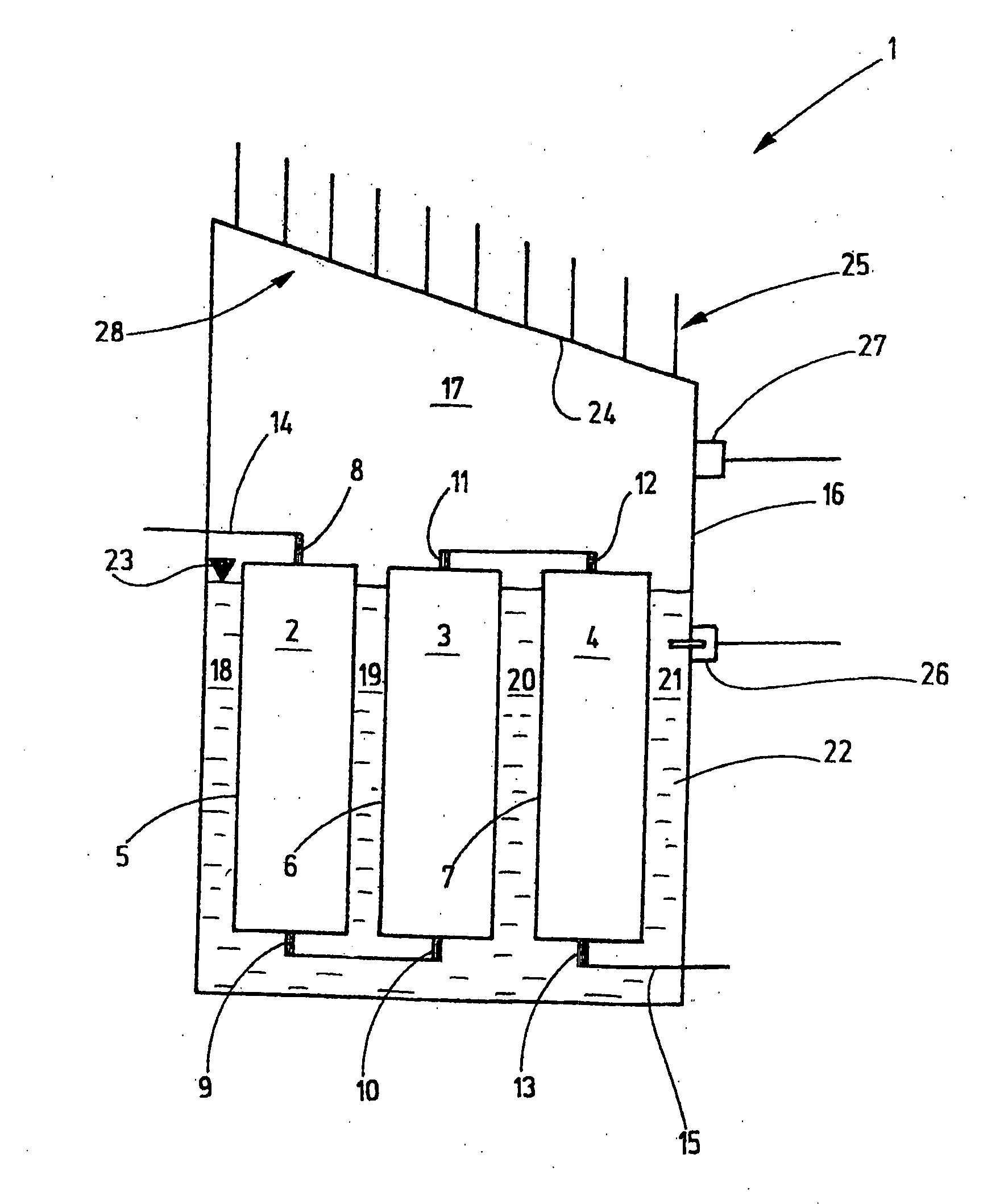
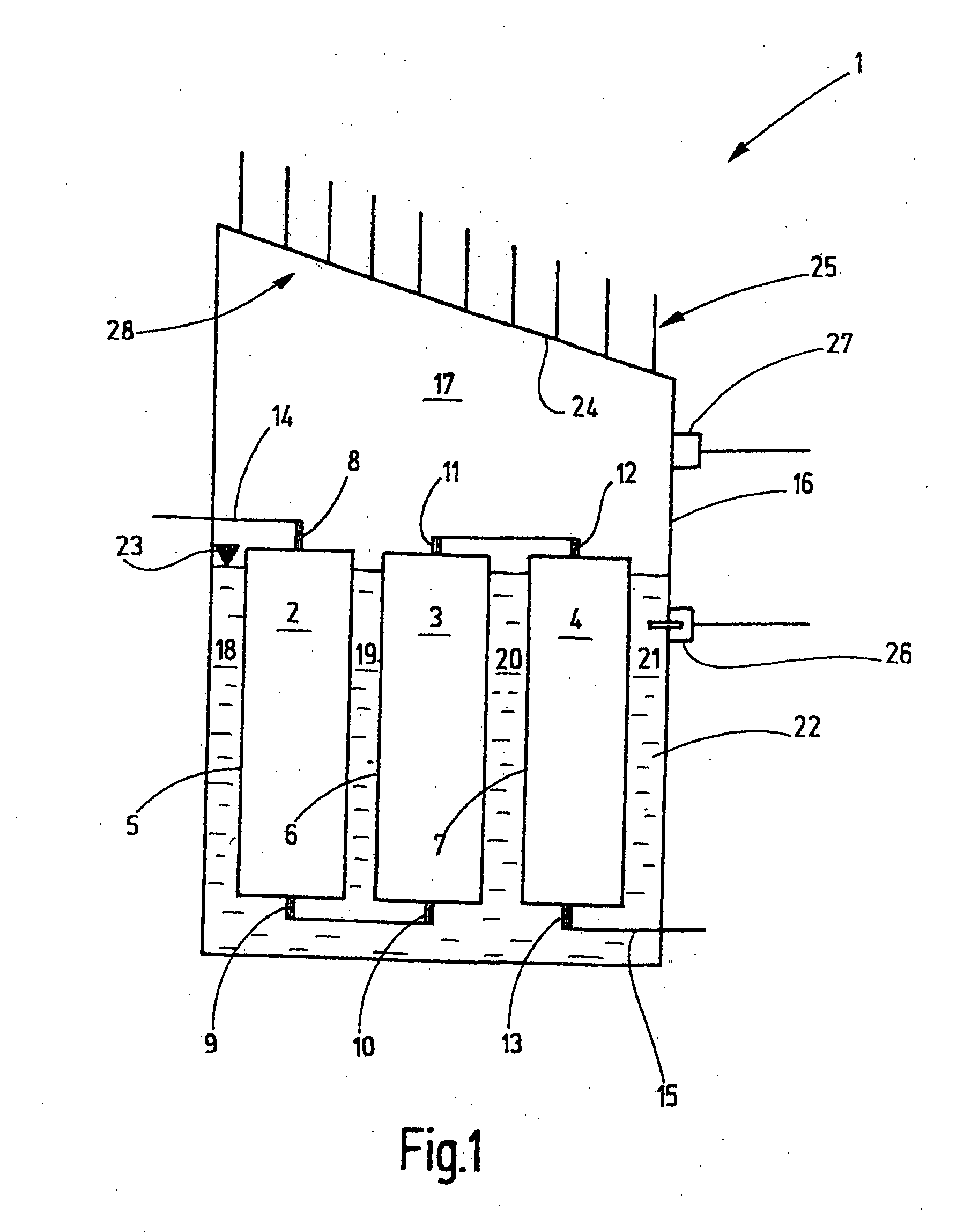
[0023]FIG. 1 shows an energy storage device 1 as it may be used, for example, as an energy buffer for a press installation including, for example, a drawing press according to DE 198 21 159 A1 or another conventional press with a motor-driven plunger and a hydraulic drawing cushion and additional presses. The energy storage device 1, however, is particularly suitable for presses and other machine tools with one or several servo drives which are periodically accelerated and decelerated, particularly if those drives are associated with relatively large dynamic loads.

[0024]The energy storage device 1 includes one or several electric capacitors 2, 3, 4 which are preferably electric double layer capacitors, so-called Super Caps or also Ultra Caps. They have each a capacity of several hundred to several thousand farads. The individual capacitors or capacitors 2, 3, 4 have generally, a relatively low maximum voltage of, for example, 2.5 volt. For increasing the available voltage, several s...


PUM


Abstract

In an energy storage device (1) with evaporation cooling wherein the boiling temperature of a liquid which is disposed in heat exchange relationship with electric capacitors (2, 3, 4) for limiting the operating temperature of the electric capacitors, a thermal vapor condensing arrangement is provided for condensing the vapors formed from the liquid during cooling of the electric capacitors and returning the condensate back to the liquid surrounding the electric capacitors.

Description

CROSS-REFERENCE TO RELATED APPLICATION[0001]This application claims the priority benefits of German Application No. 10 2006 058 629.8 filed Dec. 13, 2006.BACKGROUND OF THE INVENTION[0002]Drives for press installation, presses or other manufacturing equipment often have energy requirements which are very variable. The drives which draw their energy via intermediate converters from an energy supply system. The different energy requirements of the various drives are superimposed establishing an overall energy requirement which varies with time. With the introduction of modern converter installations are increasingly capable to field energy taken out of the energy supply system at least partially back into the power supply system. For example, energy may be energy may be taken out of this energy supply system for accelerating a drive. However, when the drive is to be shut down again energy may be returned to the energy supply system. This increases the changes in the power requirements ...

Claims


Application Information

Patent Timeline
IPC IPC(8): H01G2/08H01G2/10
CPCH01G2/08
Inventor FAHRENBACK, JURGEN
Owner SCHULER PRESSEN GMBH & CO KG
Why Eureka
Try Eureka